- 5 -
◆
Connection Method
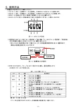
Use this product as following.
1) Connect G1 port with another DMC-1000TS-DC or a 1000BASE-T compatible unit by a single mode
optical cable.
2) Connect G2 port with a 1000BASE-SX compatible unit by a multi-mode optical cable..
3) Check the connection of optical fiber cables to OPT port
4) Please confirm that the DIP switch is set up as shown in figure 5.1.(Only pin 3 ON)
1
2
3
4
ON
DIP
10
0
E
E
E
L
F
P
10
00
D
IS
D
IS
【
ON
】
【
OFF
】
Figure 5.1 DIP switch setting
5) With the power line "+" side wired to "V 1 +" or "V 2 +" of the power terminal block, the power line "-"
side wired to "V 1 -" or "V 2 -", and the grounding wire wired, DC 12 Turn on ~ 48V power supply.
(By supplying the power supply system separately as shown in Figure 5.2, operation of this product
can also be continued with the power system remaining when one side power supply path error
occurs)
V
2
+
V
2
-
V
1
+
V
1
-
Power supply
system 1
Power supply
system 2
-
+
+
-
Earth wire
Figure 5.2 Power supply wiring (redundant power supply)
6) The PWR LED will light, "G1", "G2" LEDs will light up or flash, and communication will start.
Table 5.1 LED display pattern
LED
Color
State
Description
PWR1
Amber
●
Power is being supplied to the power input (V1+, V1-)
○
Power is not being supplied to the power input (V1+, V1-)
PWR2
Amber
●
Power is being supplied to the power input (V2+, V2-)
○
Power is not being supplied to the power input (V2+, V2-)
G1
Green
●
TP port’s 1000 Mbps link is active
※
◎
Data is being transmitted at 1000 Mbps
○
TP port’s 1000 Mbps link is inactive
Amber
●
TP port’s 10/100 Mbps link is active
※
◎
Data is being transmitted at 10/100 Mbps
○
TP port’s 10/100 Mbps link is inactive
G2
Green
●
Fiber port’s 1000 Mbps link is active
◎
Data is being transmitted at 1000 Mbps
○
Fiber port’s 1000 Mbps link is inactive
●:
On
○:
Off
◎
:
Blinking
※
Data transmission / reception is not possible. Please check the communication settings on
the connected device side.


