background image

English-21

English

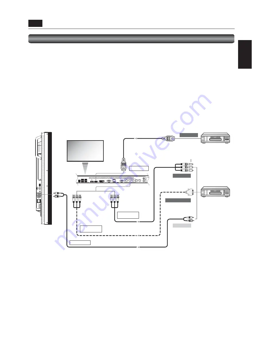
HDMI cable

 DVD/HD IN
 (Y·Pb·Pr, Y·Cb·Cr)

 DVD/HD IN
 (Y·Pb·Pr, Y·Cb·Cr)

 AUDIO IN2 (RCA)

 RGB1 IN (HDMI)

 To D connector output 

 To video output 

 To HDMI output 

 To audio output 

Audio cable (RCA)

Signal cable
(BNC x 3 to D connector)

BNC cable
(BNC x 3 to BNC x 3)

BNC – RCA adaptor

Connecting a video device (component video/HDMI device)

This monitor can be connected to a video device equipped with component output such as a DVD player. 

Refer to the user’s manual of the connected device for details. (Cables shown in the fi gure below are commercially available.) 

• 

To connect a DVD player equipped with component output to the DVD/HD IN connector (YPbPr or YCbCr) on the monitor, use a 

BNC cable (BNC x 3 – BNC x 3) and a BNC – RCA adaptor (commercially available), or a signal cable (BNC x 3 – D connector). 


Select [DVD/HD] using the INPUT button on the monitor or the YPbPr button on the wireless remote control. 

• 

To make audio connection, connect an audio cable (RCA) to the AUDIO IN2 connector or the AUDIO IN3 connector.


Select [AUDIO2] or [AUDIO3] using the AUDIO INPUT buttons on the wireless remote control.

• 

To connect a DVD player equipped with HDMI output to the RGB1 IN connector (HDMI) on the monitor, use an HDMI signal 

cable. 


Select [RGB1] using the INPUT button on the monitor or the HDMI button on the wireless remote control. 

• 

For HDMI cable connection, select HDMI audio. 


(You can select HDMI audio only when the video input is [RGB1].) 

DVD player

(component device)

Front of LCD monitor

DVD player

(HDMI device)

 P-4 

  Connection procedure (continued)

Left side of LCD monitor

Содержание D20433

Страница 1: ...54 6 LCD Display Monitor MODEL ...

Страница 2: ......

Страница 3: ...nnection English 24 Connecting OPS compliant computer English 26 P 6 Connecting RS 232C English 27 Monitor control via RS 232C English 27 P 7 Connecting LAN English 28 Monitor connection using LAN English 28 P 8 Connecting a USB device English 29 Connecting multiple USB devices using the USB hub function English 29 P 9 Connecting the power cord to the monitor English 30 Connecting the power source...

Страница 4: ...ideo content from different inputs to be displayed on certain monitors within the same installation according to the schedule and extends the monitor s life and saves the power by turning it off during those hours or days it is not in use Screen saver Functions Page 52 To reduce image persistence and maximize the panel life in demanding signage applications this product is equipped with four scree...

Страница 5: ...nvironment This equipment generates uses and can radiate radio frequency energy and if not installed and used in accordance with the instruction manual may cause harmful interference to radio communications Operation of this equipment in a residential area is likely to cause harmful interference in which case the user will be required to correct the interference at his own expense 3 You are cautio...

Страница 6: ...ERVICEABLE PARTS INSIDE REFER SERVICING TO QUALIFIED SERVICE PERSONNEL This symbol warns user that uninsulated voltage within the unit may have sufficient magnitude to cause electric shock Therefore it is dangerous to make any kind of contact with any part inside this unit This symbol alerts the user that important literature concerning the operation and maintenance of this unit has been included T...

Страница 7: ...can be recycled and or reused This symbol means that electrical and electronic equipment batteries and accumulators at their end of life should be disposed of separately from your household waste If a chemical symbol is printed beneath the symbol shown above this chemical symbol means that the battery or accumulator contains a heavy metal at a certain concentration This will be indicated as follow...

Страница 8: ...e LCD monitor is damaged and the liquid crystal leaks out do not inhale or swallow it Allow adequate ventilation around the monitor so that heat can properly dissipate Do not block ventilated openings or place the monitor near a radiator or other heat sources Do not put anything on top of the monitor The power cable connector is the primary means of detaching the system from the power supply The m...

Страница 9: ...her regions use a power cord that matches the AC voltage of the power outlet and has been approved by and complies with the safety standard of those regions or countries The following components are supplied as option External Speakers Stands CAT5 Tx BOX CAT5 Rx BOX SDI BOX Clamper x 2 To prevent from falling Screw for Clamper M4 x 2 Clamper x 2 For preventing disconnection of the power cord and H...

Страница 10: ...d Power indicator Remote control sensor Receives the signal from the wireless remote control Power indicator Indicates the state of the LCD monitor Steady green The power is on Steady red The power is off Some operations such as power on are possible Steady green and red The LCD monitor is in the sleep mode Off The main power is off Steady red and blinking green The LCD monitor is in the schedule ...

Страница 11: ...tor MINI DIN 4 pin VIDEO IN BNC connector RCA connector VIDEO OUT BNC connector NOTE The video input connectors BNC RCA cannot be used at the same time Use either BNC connector or RCA connector Connectors and Terminals R B H V G Cr Pr Cb Pb Y IN IN IN OUT IN OUT R L 10 EXTERNAL SPEAKER TERMINAL Connects with the special stereo speakers option 11 AUDIO OUT RCA Outputs the signal that is supplied to...

Страница 12: ... displayed in the sub picture CHANGE button Changes the main picture with the sub picture Description PIP Picture in Picture The sub picture is displayed within the main picture POP Picture out Picture The sub picture is displayed to the bottom right of the main picture SIDE BY SIDE The main picture and the sub picture are displayed side by side NOTE When the screen size is CUSTOM or REAL the PIP ...

Страница 13: ...Parts Name and Functions continued Installing and removing the wireless remote control batteries The wireless remote control is powered by 1 5 V AAA batteries How to install the batteries 1 Unlock and pull up the cover in the arrow s direction 2 Align the batteries according to the and indications inside the case 3 Replace the cover How to remove the batteries 1 Unlock and pull up the cover in the...

Страница 14: ...S 232C Connecting LAN Monitor connection using LAN Connecting a USB device Connecting multiple USB devices using the USB hub function Installing the monitor Installing and removing the stands The stands are optionally available Using the wall mount or ceiling mount Installing in the portrait or face up position Using the monitor without the bezel Pages 14 to 16 Page 17 Page 27 Page 28 Page 29 Page...

Страница 15: ...rong enough to bear the weight of the monitor MDT551S approximately 38 6 kg with the optional stands When using screw hooks commercially available use ring hooks not C hooks with opening CAUTION The effect of the fall prevention substantially depends on the strength of brackets and base to which the fall prevention devices is attached When you cannot ensure sufficient strength provide adequate rein...

Страница 16: ...the bracket manufacturer for installation location To lessen the risk of falling of the monitor thread commercially available rope through the handles at the right and left of the monitor and secure the rope to the wall mount brackets or ceiling mount brackets Do not sleep where the monitor may topple over or fall in case of an earthquake or other disaster Use screws having enough strength to supp...

Страница 17: ...etc In the portrait position the lifetime of the fluorescent tube backlight is shorter than that when the monitor is in the landscape position When installing the monitor with its screen facing up ensure that the fan is always running Installation in the portrait position The logo should be on the LEFT side when viewed from the front of the monitor Installation in the face up position Operation env...

Страница 18: ...emble the supplied protective cover according to the following procedure 2 Unscrew the screws a that hold the bezel to remove the bezel from the monitor CAUTION If you remove other screws than the screws a the bezel falls apart If you do so the bezel may fall causing injury or damaging the monitor a a 3 Peel off the separators from the protective cover b assembled in step 1 and then attach the pro...

Страница 19: ...ker Before making connections Optional speakers can be installed Please refer to Quick Setup Guide of the optional speakers for the detailed installation procedure How to install the optional speakers 1 Install the optional speakers on the monitor Use the metal fittings and screws supplied with the optional speakers 2 Insert the left speaker cable into the SPEAKER S terminal L on the monitor and in...

Страница 20: ...monitor DVD player or HD disk player HDMI BNC VCR RCA Stereo amplifier External speakers Clamper Clamper Before making connections First turn off the power of all the connected equipment before making connections Refer to the user manual of each piece of equipment NOTE Please use the audio cable without resistance when the audio output terminal of the audio device and PC is stereo mini Jack When th...

Страница 21: ...x 5 commercially available to connect to the mini D SUB 15 pin connector on the computer 2 Select RGB4 using the INPUT button on the monitor or the BNC button on the wireless remote control Second monitor connection Connect the RGB OUT connector mini D SUB 15 pin on the first monitor and the RGB3 IN connector mini D SUB 15 pin on the second monitor using a signal cable mini D SUB 15 pin mini D SUB ...

Страница 22: ...audio cable ø3 5 mm stereo mini commercially available to the AUDIO IN1 connector Select AUDIO1 using the AUDIO INPUT buttons on the wireless remote control When an HDMI cable is connected select HDMI audio You can select HDMI only when the video input is RGB1 Left side of LCD monitor Front of LCD monitor P 4 Connection procedure continued The monitor automatically distinguishes the timings shown ...

Страница 23: ...use a BNC cable BNC x 3 BNC x 3 and a BNC RCA adaptor commercially available or a signal cable BNC x 3 D connector Select DVD HD using the INPUT button on the monitor or the YPbPr button on the wireless remote control To make audio connection connect an audio cable RCA to the AUDIO IN2 connector or the AUDIO IN3 connector Select AUDIO2 or AUDIO3 using the AUDIO INPUT buttons on the wireless remote...

Страница 24: ...IN connector select VIDEO S using the INPUT button on the monitor or the VIDEO S button on the wireless remote control To connect two monitors connect one end of a BNC cable to the VIDEO OUT connector of the first monitor and the other end to the VIDEO IN connector of the second monitor NOTE When different monitors need to be adjusted so that their tint can be identical such as when using multiple ...

Страница 25: ...nect the third and later monitors in the same way You can connect up to 25 monitors Allowable cable length Connection Max cable length SD SDI HD SDI 3G SDI One monitor 300 m 200 m 100 m Multiple monitors total cable length 350 m 250 m 150 m The lengths given above are based on the actual measurements using our standard signal source and the recommended cable as follows Before installation check th...

Страница 26: ... the computer from the CD ROM supplied with the CAT5 Tx BOX Installing the USB driver isn t necessary when the communication control isn t used or the RS 232C cable is used for connection OS supported Windows XP Windows Vista Windows 7 How to install Start the PL2303_Prolific_DriverInstaller_v exe file in the Windows folder on the CD ROM supplied with the CAT5 Tx BOX option and install the driver ac...

Страница 27: ... transmission involves certain amount of image quality degradation digital data transmission such as SDI connection is recommended for high definition video transmission Allowable cable length Connection Max cable length signal timing One monitor 150 m 1920 x 1080 60 Hz Multiple monitors 200 m 1920 x 1080 60 Hz Total length of the connected cables The lengths given above are based on the actual mea...

Страница 28: ...nitor and disconnect the power cord CAUTION Be sure to disconnect the power cord to prevent breakdown and electric shock 2 Use a Phillips screwdriver to unscrew and remove the option slot cover Retain the screw for later use in step 4 3 Mount a OPS compliant computer commercially available on the option slot of the monitor CAUTION To prevent damage please ensure proper orientation and position of ...

Страница 29: ...nd this monitor using a reverse type RS 232C cable commercially available In addition when you connect two or more monitors as shown in the illustration below connect the RS 232C OUT connector of the first monitor and the RS 232C IN connector of the second monitor using a reverse type RS 232C cable commercially available By repeating the connection in the similar way you can connect monitors in a d...

Страница 30: ...ype LAN cable commercially available When you connect two or more monitors you can connect the monitor and the LAN hub using a straight type LAN cable commercially available as described above CAUTION Do not connect the CAT5 IN or the CAT5 OUT connector to the LAN connector If connected both of the connectors may fail NOTE When you use a cross type LAN cable commercially available you can connect ...

Страница 31: ...cable commercially available When using an OPS compliant computer Install an OPS compliant computer connected internally 2 Connect a USB device to the downstream port of this monitor NOTE The USB hub function cannot control the monitor Use CAT5 Tx BOX option and CAT5 Rx BOX option to control the monitor from a USB device See pages 23 and 44 Up to 5 hubs can be cascaded in the hub function of this ...

Страница 32: ...ould be installed as near the equipment as possible and should be easily accessible Fully insert the prongs into the power outlet socket Loose connection may cause noise Don t plug and unplug the power cord repeatedly in a short time of period NOTE Please refer to Safety Precautions Maintenance Recommended Use in this manual for proper selection of the AC power cord Use the clamper to prevent acci...

Страница 33: ...7 Page 38 Page 38 Pages 39 to 40 Pages 41 to 43 Page 44 Turning on all the connected devices Selecting the video input Controlling the external devices Selecting the OSD language RGB3 RGB4 and OPTION CAT5 only Auto setup Selecting the picture mode Screen adjustment Picture adjustment Volume and tone control Speaker setting Schedule setting Remote control Setting the USB device How to Use ...

Страница 34: ...e computer to complete the startup process NOTE If the computer doesn t reply to the monitor for about one minute an error message OPTION ERROR is displayed See the user s manual of your computer 2 Turn on the Main Power Switch The power indicator turns on green and the monitor turns on The control buttons on the rear of the monitor and the wireless remote control don t work while the Main Power S...

Страница 35: ... RGB1 2 3 4 OPTION CAT5 or RGB6 is terminated the monitor will be in the sleep mode in several seconds VIDEO When the sync signal of video input DVD HD VIDEO S or VIDEO is terminated the monitor will be in the sleep mode in approximately 10 minutes Description DPM Acronym for Display Power Management NOTE The default power management settings power savers for RGB and VIDEO are ON When an OPS compl...

Страница 36: ...ton on the monitor the video input OSD menu is displayed and you can select the video input using the and buttons Selectable video inputs are RGB1 HDMI RGB2 DVI D RGB3 D SUB RGB4 BNC OPTION RGB6 DISPLAY PORT DVD HD YPbPr VIDEO S and VIDEO When you press the INPUT button again the selected video input is displayed OPTION can be used when an extension module is mounted on the option slot NOTE The se...

Страница 37: ...D language Display the OSD menu by pressing the MENU button on the wireless remote control or the EXIT button on the rear of the monitor Using LANGUAGE in the CONFIGURATION1 menu of the OSD screen function you can select the OSD language See page 52 U 3 Controlling the external devices VCR etc Personal computer ...

Страница 38: ...E The auto setup works on RGB3 RGB4 and OPTION CAT5 only U 6 Selecting the picture mode Using the PICTURE MODE button on the wireless remote control you can select the picture mode suitable for images to be displayed Auto setup or Displaying the OSD menu HIGHBRIGHT The brightness is maximized STANDARD Factory default setting sRGB Suitable for color matching with sRGB compliant devices CINEMA Suita...

Страница 39: ...lutions to obtain proper screen condition NOTE The position adjustment works on RGB3 RGB4 OPTION CAT5 DVD HD VIDEO S and VIDEO only The clock adjustment and the resolution adjustment work on RGB3 RGB4 and OPTION CAT5 only The zoom adjustment works on all video inputs U 8 Picture adjustment Display the OSD menu by pressing the MENU button on the wireless remote control or the EXIT button on the rea...

Страница 40: ... control Alternatively display the OSD menu by pressing the MENU button on the wireless remote control or the EXIT button on the rear of the monitor Using the AUDIO menu of the OSD screen function you can adjust the balance treble and bass NOTE If no audio is output when an OPS compliant computer is in use check that the monitor is selected as the audio output source by the operating system of the...

Страница 41: ...he MENU button on the wireless remote control or the EXIT button on the rear of the monitor Using SCHEDULE in the CONFIGURATION2 menu of the OSD screen function you can program power on off and input selection U 11 Schedule setting Carry out as necessary ...

Страница 42: ...enter INPUT Set the video input to be selected when the power is turned on If you want to select the video input that was selected before the power is turned on enter EVERY DAY Select this option to execute the schedule every day When you select EVERY DAY you cannot select any days of the week and EVERY WEEK MON SUN Select the days of the week on which you want to execute the schedule Unless you s...

Страница 43: ...lect either of the following two transmission reception control modes using the COM MODE switch LEGACY DP 1CA5 T compatible mode The RXD TXD RTS DTR and GND lines are used For a control program RTS and DTR as transmit control signals of negative logic are used The transmission period of TXD and the hold time of 70 ms are defined as Sending Low and the subsequent processes as Receiving High AUTO RTS...

Страница 44: ...tion commands configure the basic operation settings of this LCD monitor The commands may not work during signal switchover The operation commands have no data codes Operation ASCII HEX POWER ON 21h POWER OFF 22h Turn off the power forcefully 22h 22h INPUT RGB 1 _r1 5Fh 72h 31h INPUT RGB 2 _r2 5Fh 72h 32h INPUT RGB 3 _r3 5Fh 72h 33h INPUT RGB 4 _r4 5Fh 72h 34h INPUT OPTION _r5 5Fh 72h 35h INPUT RGB...

Страница 45: ...upply Resolution 1 C tc2 ex 31 74 63 32 2B 20 33 31 OPTION can be used when an extension module is mounted on the option slot NOTE The monitor will acknowledge the power on off command issued from the OPS compliant computer however it will not execute the command This is not a malfunction For automatic operation use SCHEDULE in the CONFIGURATION2 menu of the OSD screen function LAN Remote control ...

Страница 46: ...S to be used 2 Check that the USB hub is recognized The USB hub of this monitor is detected by the computer and the OS standard device driver is installed automatically Some computers may not recognize the USB hub even if it is connected In such a case install the device driver for the USB hub referring to the user s manual of the computer NOTE It takes several seconds for the computer to recogniz...

Страница 47: ...ayed out Sub menu screen When you select a sub menu an OSD screen is displayed Sub menus contain information screens adjustment menu screens and selection menu screens as shown below Sub menu screen Picture reset for example Page 47 Page 49 Page 50 Page 51 Page 52 Page 53 Page 55 Configuration of OSD screen This monitor is equipped with the OSD On Screen Display function for easy screen adjustment ...

Страница 48: ...essing the or button Accept the selected sub menu by pressing the SET button Accept the selected sub menu by pressing the INPUT button Select the setting value by pressing the or button and then press the SET button to accept the setting Select the setting value by pressing the or button and then press the INPUT button to accept the setting The OSD screen disappears when you press the MENU button ...

Страница 49: ...the TINT screen appears and you can adjust the following TINT You can adjust all the colors at the same time Press the PLUS button to add a green tint Press the MINUS button to add a purple tint RED MAGENTA BLUE CYAN GREEN or YELLOW You can adjust each color individually Press the PLUS button to shift the selected color to the right around the color circle Press the MINUS button to shift the selec...

Страница 50: ...r to configure the monitor as Slave when controlling multiple monitors collectively LIGHT FROM BACK When a light source such as a light and a window is behind the monitor the rear sensor takes precedence YES Select this setting when there is a light source such lighting equipment and a window behind the monitor NO Select this setting when there is no light source such lighting equipment and a windo...

Страница 51: ...hed to fill the screen with different magnifications at the screen center and the screen edges CUSTOM You can stretch the image horizontally and vertically as you desire using the CUSTOM ZOOM setting REAL The image is displayed without being stretched or reduced NOTE In the DYNAMIC mode the top and the bottom of the image may be cropped Full HD images are displayed as in the FULL mode CUSTOM ZOOM CU...

Страница 52: ...e treble sound Press the MINUS button to decrease the treble sound BASS You can adjust the low frequency sound Press the PLUS button to increase the bass sound Press the MINUS button to decrease the bass sound SPEAKER You can switch the built in speakers and external stereo speakers option INTERNAL To output from the built in speakers Maximum output 10 W 10 W EXTERNAL To output from external speak...

Страница 53: ... is output PIP H POSITION You can adjust the horizontal position of the sub screen Press the PLUS button to move the sub screen to the right Press the MINUS button to move the sub screen to the left PIP V POSITION You can adjust the vertical position of the sub screen Press the PLUS button to move the sub screen up Press the MINUS button to move the sub screen down SUB INPUT You can select the vid...

Страница 54: ...ing fan always runs When you select AUTO the built in fan automatically starts running according to the operating temperature BRIGHTNESS When you select ON the brightness decreases MOTION The screen slightly moves horizontally and vertically at regular intervals to reduce the effect of the image persistence NOTE When you select a time period in the MOTION setting the monitor enlarges the image and...

Страница 55: ... communication function For connection of the signal cable see page 23 to 29 RS485 TERMINATION RS 485 can be set only when an optional CAT5 Rx BOX is mounted on the option slot Turn ON or OFF the termination resistance of the RS 485 interface ON Select this setting to use the monitor alone or to configure the monitor as the one at the end of the connection when more than one monitor is multi connec...

Страница 56: ... day of week the monitor is activated and which input source the monitor will use for each scheduled activation period A check mark in the box next to the number of the schedule indicates that the selected schedule is in effect To select which schedule to set use the up down arrows to move the number 1 to 7 of the schedule Use the and buttons to move the cursor horizontally within the particular s...

Страница 57: ...verted Though this setting is suitable for motion images still images aren t displayed properly FILM MODE You can select the film mode function AUTO Images of 24 frames per second are detected subjected to interpolation and then displayed OFF The input video signals are displayed without being subjected to any processing NOTE When FILM MODE is AUTO set SCAN CONVERSION to PROGRESSIVE See page 55 IR ...

Страница 58: ...laying the RGB1 HDMI signal Select FULL when displaying the signal that uses all 256 levels from level 0 to 255 This mode is used primarily when input comes from a computer Select LIMITED when displaying the signal that uses 16 to 235 levels of 256 levels for each of R G and B This mode is used primarily when input comes from a video device HDMI MODE Select this setting when displaying the RGB1 HD...

Страница 59: ...k the operation buttons By holding down both the and button on the monitor for 3 seconds or longer again you can unlock the operation buttons NORMAL NORMAL DYNAMIC NORMAL Squeeze signal NORMAL FULL Normal size of each signal Recommend picture size OSD information OPTION SDI 3G 1920 x 1080 67kHz 60Hz AUDIO SDI SIZE FULL DVD HD AUDIO 3 SIZE FULL VIDEO S NTSC AUDIO 3 SIZE NORMAL RGB2 1024 x 768 48kHz...

Страница 60: ...DIO3 RGB4 BNC AUDIO1 AUDIO2 AUDIO3 OPTION Audio supported For OPS compliant computer OPTION AUDIO1 AUDIO2 AUDIO3 Audio supported For SDI BOX SDI AUDIO1 AUDIO2 AUDIO3 Audio not supported AUDIO1 AUDIO2 AUDIO3 RGB6 DISPLAY PORT DP AUDIO1 AUDIO2 AUDIO3 DVD HD YPbPr AUDIO1 AUDIO2 AUDIO3 VIDEO S AUDIO1 AUDIO2 AUDIO3 VIDEO AUDIO1 AUDIO2 AUDIO3 OPTION can be used when an extensiton module is mounted on th...

Страница 61: ...ntrol the monitors When using a computer to control the monitors you must prepare an application software program for control by yourself Brightness of all the monitors can be controlled centrally using a computer if the customer create a control application to remotely read the value from two brightness sensors of any monitor and distribute it to all monitors 1 Connect the RS 232C IN connector of...

Страница 62: ...mounted on the option slot By pressing the PIP ON OFF button on the wireless remote control you can change the PIP POP and SIDE BY SIDE modes in the order shown below Alternatively you can change the modes using the PIP MODE setting of PIP in the OSD main menu See page 51 The resolutions in the PIP POP and SIDE BY SIDE FULL modes are as follows PIP SIZE SMALL 450 pixels X 338 pixels MIDDLE 675 pix...

Страница 63: ...gnal sensor of the PRIMARY monitor OSD appears on the monitor having the ID number you selected NOTE When the ID selection OSD is being displayed on the PRIMARY monitor press the DISPLAY button on the remote controller again to cancel the ID selection OSD and then control the monitor you selected If you set the remote control mode wrongly and remote control operation becomes unavailable press any ...

Страница 64: ... may need to be re adjusted Check the monitor and your display card with respect to the compatibility and recommended signal timings If the displayed text is garbled change the video mode to the non interlace mode and use 60 Hz refresh rate Image of component signal is greenish Check to see if the DVD HD input connector is selected LED on the monitor is not lit No green or red color can be seen Po...

Страница 65: ...ted Resolution Composite Separate NTSC PAL SECAM 4 43 NTSC PAL60 Component 480i 480p 576i 576p 1080i 720p 1080p SDI 480i 576i SD SDI 720p 1080i HD SDI 1080p 3G SDI Audio Input Output Input Connector Analog RCA pin jack L R x 2 ø3 5 mm stereo mini jack PC audio Digital HDMI digital audio Output Connector RCA pin jack L R External speaker output Speaker connector L R impedance 8 Ω Option slot Slot i...

Страница 66: ...a1 Shield 12 TMDS Clock 19 Hot Plug Detect 6 TMDS Data1 13 CEC 7 TMDS Data0 14 Reserved N C on device 3 Digital RGB input DVI D RGB2 Pin Assignment of DVI D connector 1 TMDS Data2 9 TMDS Data1 17 TMDS Data0 2 TMDS Data2 10 TMDS Data1 18 TMDS Data0 3 TMDS Data2 Shield 11 TMDS Data1 Shield 19 TMDS Data0 Shield 4 NC 12 NC 20 NC 5 NC 13 NC 21 NC 6 DDC Clock 14 5V Power 22 TMDS Clock Shield 7 DDC Data ...

Страница 67: ...DEO input MINI DIN 4 pin VIDEO S Pin No Name 1 GND 2 GND 3 Y Luminance 4 C Chroma 6 RS 232C input output Pin No Name 1 NC 2 RXD 3 TXD 4 NC 5 GND 6 NC 7 NC 8 NC 9 NC 7 LAN Modular 8 pin Pin at RJ45 Signal Pair 1 Orange White stripe 2 Orange 3 Green White stripe 4 Blue 5 Blue White stripe 6 Green 7 Brown White stripe 8 Brown ...

Страница 68: ......

Страница 69: ...ielectric com tw 11th Floor 88 Sec 6 Chung Shan N Road Taipei 111 Taiwan Sales Phone 886 2 28328255 Fax 886 2 28339813 Technical Phone 886 2 28328255 ext 3420 Fax 886 2 28339813 India Mitsubishi Electric India Pvt Ltd http www mitsubishielectric in Building No 9B dlf Cyber City Phase3 Gurgaon Delhi India Sales Phone 91 0124 4630300 Fax 91 0124 4630399 E mail hitesh bhardwaj asia meap com Technical...

Отзывы: