G
B
GB-45
WT08432X01
・
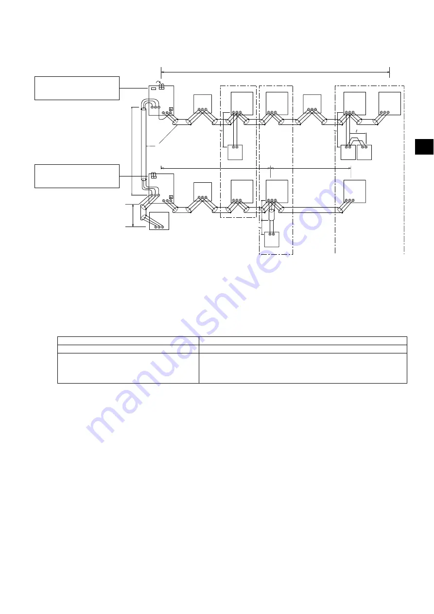
System configuration example
* The numbers in the parentheses in the figures below indicate address numbers.
(1) When ME remote controllers are connected
M1M2
M1M2 S
TB7
TB3
IC
(51)
M1
M2 S
TB5
ME
(01)
IC
M1
M2 S
TB5
(02)
IC
M1
M2 S
TB5
(04)
IC
M1
M2 S
TB5
(03)
IC
M1
M2 S
TB5
(05)
IC
M1
M2 S
TB5
(07)
IC
M1
M2 S
TB5
(06)
L
2
L
1
(101)
ME
(105)
ME
(103)
ME
(155)
M1M2
M1M2 S
TB7
TB3
CN41
(53)
OC
A B S
L
3
L
6
L
4
L
5
A B
A B
A B
A B
BC
M1
M2 S
(52)
BS
M1
M2 S
(55)
BC
M1
M2 S
(54)
TB02
TB02
TB02
111
444
222
3
3
3
OC
CN41
CN41 CN40
Ⓒ
Ⓐ
Ⓑ
Ⓐ
Shielded cable
Ⓑ
Sub remote controller
Ⓒ
System controller
*1 When a power supply unit is not connected to the centralized control transmission cable, move the power jumper from CN41 to CN40 on
only one of the outdoor units.
*2 If a system controller is used, set SW5-1 on ALL of the outdoor units to ON.
*3 In an R2 system: BC, BS
In a Hybrid City Multi system: HB, HS
Maximum allowable length of control cables
Transmission cables via outdoor units
L
1
+ L
2
+ L
3
+ L
4
, L
1
+ L
2
+ L
3
+ L
5
, L
1
+ L
2
+ L
6
PIW
*4
Transmission cables
L
1
, L
3
+ L
4
, L
3
+ L
5
, L
6
, L
2
+ L
6
PIW
Remote controller cables
Ɛ
1
Ɛ
2
Ɛ
3
Ɛ
4
PIW
* If the length exceeds 10 m (32 ft), the length that exceeds 10 m (32 ft) needs
to be included in the maximum allowable length of transmission cables
above.
*4 When extending the length of the transmission cables to 1000 m (3280 ft), consult your dealer.
*3
*3
*3
* Leave the power jumper
connected to CN41.
* SW5-1: ON *
2
* Move the power jumper from
CN41 to CN40. *
1
* SW5-1: ON *
2
Group 1
Group 3
Group 5
Содержание City Multi R2 Series
Страница 2: ......
Страница 62: ...GB 60 WT08432X01 ...


