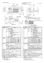
3.各部の名称と設定
3. Part Names and Settings
4.
5
(0
.1
8)
100
(3.94)
4
(0.16)
50
(1
.9
7)
8.5
(0.
33
)
114±0.5 *1
(4.49±0.02) *1
3
3±0
.3
*
1
(
1.
30±
0.
01)
*1
8
F
9 A B C D E
B
RATE
24
1
4
22
0
1
0
7
1 2 3 4 5 6
ST
AT
IO
N NO.
81
0
ON
PW
L RUN L ERR.
40
C
B
A
D
CON
X
8
F
E
D
C
B
A
9
X
0
7
6
5
4
3
2
1
AJ65VBTCE3-16D
41.5(1.63)
23.
5
(
0.93
)
③
②
①
⑥
⑧
④ ⑤
⑦
⑧
DIN rail center
DINレール中心
2-M4取付ネジ穴
2-M4 installation screw hole
1
6.5
(0.
65)
3
1 (1
.2
2)
31.
5
(
1.24
)
5
(
0.20
)
4
(0.16)
8.5
(0.33)
⑨
64±
0
.3
*
1
(
2
.52±
0.
01
) *
1
⑨
41.5
(1.63)
⑦
83±0.5 *1
(3.27±0.02) *1
5.0
(0.20)
1
3.5
(0
.5
3)
1
3.5
(
0.53
)
13.5
(0.53)
DIN rail center
DINレール中心
13.5
(0.53)
Unit : mm(inch)
<DINレール取付方向>
DINレールを横方向と縦方向の2方向で取付けることが可能です。
<DIN rail mounting orientation>
DIN rail can be set in two orientations (lateral or vertical).
DINレール(縦方向)
DIN rail (Vertical orientation)
8
F
9 A B C D E
B
RATE
24
1
4
22
0
1
0
7
1 2 3 4 5 6
S
TA
TIO
N N
O.
81
0
ON
PW
L RUN L ERR.
40
C
B
A
D
CON
X
8
F
E
D
C
B
A
9
X
0
7
6
5
4
3
2
1
AJ65VBTCE3-16D
DINレール(横方向)
DIN rail (Lateral orientation)
45.5(1.79)
*1:取付ネジ加工寸法(取付ピッチ)
No.
名称
内 容
LED名
確認内容
PW
点灯: 電源ON
消灯: 電源OFF
L RUN
点灯: 交信正常時
消灯: 交信断時
(タイムオーバエラー)
L ERR.
点灯: 交信エラー時
一定間隔で点滅:
通電中に局番設定/伝送速度設定スイッチの
設定を変更したとき
不定間隔で点滅:
終端抵抗の設定が違っているとき
ユニット,CC-Link専用ケーブルがノイズの影
響を受けているとき
消灯: 交信正常時
① 動作表示
LED
X0~F
点灯: 入力ON
消灯: 入力OFF
設定スイッチ状態
設定値
4
2
1
伝送速度
0
OFF
OFF
OFF
156 kbps
1
OFF
OFF
ON
625 kbps
2
OFF
ON
OFF
2.5 Mbps
3
OFF
ON
ON
5.0 Mbps
4
ON
OFF
OFF
10 Mbps
② 伝送速度
設定
スイッチ
伝送速度は必ず上記の範囲で設定してください。
STATION NO.の“10”,“20”,“40”で局番の10の位を設定しま
す。
STATION NO.の“1”,“2”,“4”,“8”で局番の1の位を設定し
ます。
局番は必ず1~64の範囲で設定してください。*2
(例) 局番を“32”に設定するときは,下記のようにスイッチ設
定を行います。
十の位
一の位
局番
40
20
10
8
4
2
1
32
OFF
ON
ON
OFF OFF
ON
OFF
③ 局番設定
スイッチ
④ 通信用
コネクタ
通信ラインの接続用ワンタッチコネクタ。
⑤ 電源・FG用
コネクタ
ユニット電源ライン,I/O電源ライン,FGの接続用ワンタッチコ
ネクタ。
⑥ I/O用
コネクタ
入出力信号の接続用コネクタ。
⑦ DINレール用
フック
ユニットをDINレールに取り付ける場合にDINレール用フックの
中心線上を指でカチッと音がするまで押さえます。
⑧
⑨
ネジ取付け
用固定具
(付属品)
ユニットを盤などに取り付ける場合に,ユニットに装着して使
用します。(⑧と⑨の2通りの装着が可能です。)
ネジ取付け用固定具は,取り外すことが可能です。
*2:局番は重複して設定できません。
4. 同梱品(付属品)
ネジ取付け用固定具 2 個
*1: Adjust the screws to ensure this length. (Mounting pitch)
No.
Item Description
LED name
Confirmation details
PW
ON: Power supply ON
OFF: Power supply OFF
L RUN
ON: Normal communication
OFF: Communication shut off
(time expiration error)
L ERR.
ON: Communication data error
Flash at regular intervals:
Indicates that the station number setting
or transmission speed setting switch
position was changed while power is ON
Flash at irregular intervals:
When the setting of the terminal resistor
is wrong; when the cable for the module
or CC-Link is affected by noise
OFF: Normal communication
①
Operating
status LEDs
X0 to F
ON: Input ON OFF: Input OFF
Setting switch status
Setting
value
4 2 1
Transmission
speed
0
OFF OFF OFF
156
kbps
1 OFF
OFF
ON 625
kbps
2 OFF
ON
OFF
2.5
Mbps
3 OFF
ON
ON 5.0
Mbps
4 ON
OFF
OFF
10
Mbps
②
Transmission
speed setting
switch
Be sure to set the transmission speed within the above range.
Select “10”, “20” or “40” to set the tens place of the station
number.
Select “1”, “2”, “4” or “8” to set the ones place of the station
number.
Always set the station number within the range of 1 to 64. *2
(Example) Set the switches as below when setting the station
number to 32:
Tens place
Ones place
Station
number
40
20 10 8 4 2 1
32 OFF
ON
ON
OFF OFF ON
OFF
③
Station number
setting switch
④
Connector for
communication
One-touch connector for connection of communication line.
⑤
Connector for
power supply
and FG
One-touch connector for unit power supply line, I/O power
supply line, and FG.
⑥
Connector for
I/O
Connector for connection of I/O signal.
⑦
Hook for DIN
rail
When the module is installed to the DIN rail, push on the center
line of the hook for DIN rail with a finger tip until a clicking sound
is heard.
⑧
⑨
Holding fixtures
for screw
installation
(Accessory)
When mounting a module to a panel or similar, attach the
fixtures to the module (in two positions of
⑧
and
⑨
).
Holding fixtures for screw installation are removal.
*2: Duplicate station number cannot be set.
4. Included parts (Accessory)
Holding fixtures for screw installation 2


