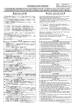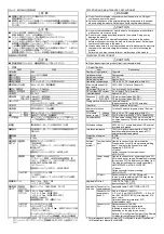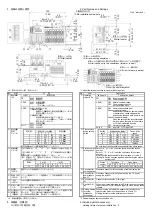
外部接続
(External connection)
ピン番号
Pin No.
信号名
Signal name
1
DA
2
DB
3
DG
4
Empty
CON A, B
5
SLD
1
(FG)
2
+24V (UNIT)
3
24G (UNIT)
4
+24V(I/O)
CON C, D
5
24G(I/O)
端子台
Terminal block
ピン番号
Pin No.
信号名
Signal
name
ピン番号
Pin No.
信号名
Signal
name
ピン番号
Pin No.
信号名
Signal
name
ピン番号
Pin No.
信号名
Signal
name
1
+24V
1 +24V
1 +24V
1
+24V
2
+V 2
+V 2
+V 2
+V
3
24G 3
24G 3
24G 3
24G
CON
1
(X0)
4
X0
CON
5
(X4)
4 X4
CON
9
(X8)
4 X8
CON
13
(XC)
4
XC
1
+24V
1 +24V
1 +24V
1
+24V
2
+V 2
+V 2
+V 2
+V
3
24G 3
24G 3
24G 3
24G
CON
2
(X1)
4
X1
CON
6
(X5)
4 X5
CON
10
(X9)
4 X9
CON
14
(XD)
4
XD
1
+24V
1 +24V
1 +24V
1
+24V
2
+V 2
+V 2
+V 2
+V
3
24G 3
24G 3
24G 3
24G
CON
3
(X2)
4
X2
CON
7
(X6)
4 X6
CON
11
(XA)
4 XA
CON
15
(XE)
4
XE
1
+24V
1 +24V
1 +24V
1
+24V
2
+V 2
+V 2
+V 2
+V
3
24G 3
24G 3
24G 3
24G
CON
4
(X3)
4
X3
CON
8
(X7)
4 X7
CON
12
(XB)
4 XB
CON
16
(XF)
4
XF
端子配列
Pin arrangement
CONB
1
DA
2
DB
3
DG
4
5
SLD
LINK CABLE
(IN)
通信用ワンタッチコネクタ
LINK CABLE
(OUT)
1
2
3
4
5
1
2
3
4
5
CONA
1
DA
2
DB
3
DG
4
5
SLD
Empty
One-touch connector for communication
COND
UNIT POWER CABLE(IN)
1
2
3
4
5
1
2
3
4
5
CONC
1
FG
2
+24V(UNIT)
3
24G(UNIT)
4
5
1
FG
2
+24V(UNIT)
3
24G(UNIT)
4
5
I/O POWER CABLE(IN)
1
2
3
4
CON1
1
2
3
4
CON16
絶縁
DC/DC
+24V(I/O)
24G(I/O)
+24V(I/O)
24G(I/O)
検出回路
1
2
3
4
CON2
3線式センサ
(シンク出力)
検出回路
1
2
3
4
CON3
2線式センサ
(シンク出力)
検出回路
UNIT POWER CABLE(OUT)
I/O POWER CABLE(OUT)
電源・FG用ワンタッチコネクタ
*1
3-wire type sensor
(sink output)
Insulation
One-touch connector for power supply and FG
Detection circuit
2-wire type sensor
(sink output)
3線式センサ
(シンク出力)
3-wire type sensor
(sink output)
黒
青
(black)
(blue)
茶
(brown)
茶
(brown)
黒
青
(black)
(blue)
茶
(brown)
青
(blue)
芯線色は,JIS C 4524による。
芯線色は,IEC60947-5-2による。
The color of core conforms to JIS C 4524.
The color of color conforms to IEC60947-5-2.
Empty
*1: 電源・FG 用コネクタのアキには必ず無配線のコネクタを装着してください。
The connector in non-divided line should be installed to empty of connector for the power
supply and FG.
ユニットの正面から見た場合
A module view from the top
C
B
A
D
CON
CON 9
16
15
14
13
12
11
10
CON
1
8
7
6
5
4
3
2
1
2
3
5
4
1
2
3
4
1
2
3
4
2.取付け方向と最大同時入力点数の制約
仕様に記載されている最大同時入力点数は,取付け方向により変
わります。
(1) 最大同時入力点数の制約のない取付け方向
図 2.1 の取付け方向の場合,最大同時入力点数に制約はありません。
(2) 最大同時入力点数の制約のある取付け方向
図 2.2~図 2.5 の取付け方向の場合,周囲温度が 55℃のとき最
大同時入力点数は 62.5%になります。
(図 2.6 ディレーティングカーブ参照)
2. Installation Orientation and Restrictions on the maximum number
of simultaneous input points
The maximum number of simultaneous input points listed in the
specifications will change, depending on the installation orientation.
(1) Installation orientations without restriction on the maximum number of
simultaneous input points.
When the module is mounted in the orientation of Fig. 2.1, maximum
number of simultaneous input points will not be restricted.
(2) Installation orientations with restriction on the maximum number of
simultaneous input points.
When the module is mounted in the orientation of Fig. 2.2 to 2.5, under
the ambient temperature of 55
℃
, maximum number of simultaneous
input points will be 62.5%. (Refer to Fig. 2.6 Derating Chart)
C
D
図 2.1 正面取付け(正方向)
Fig. 2.1 Front installation (Basic orientation)
図 2.2 正面取付け(逆方向)
Fig. 2.2 Front installation (Upside-down orientation)
図 2.3 正面取付け(縦方向)
Fig. 2.3 Front installation (Vertical orientation)
Ma
xi
mum
numb
e
r of
s
imul
tan
eous
inpu
t poi
nt
s
最
大
同
時
入
力
点
数
50
75
100
周囲温度[℃]
Ambient temperature
0
10
20
30
40
50 55
[%]
[℃]
[%]
62.5
図 2.4 天井取付け
Fig. 2.4 Ceiling installation
図 2.5 平面取付け
Fig. 2.5 Horizontal installation
図 2.6 ディレーティングカーブ
Fig. 2.6 Derating Chart


