background image

      Air Handling Unit Interface 

      AHU-KIT-SP 


MORIKAWA 

      SPECIFICATION 

PSZ000Z308 


3/38 

MODEL NAME 

MODEL TYPE 

ISSUE 

CLASSIFICATION 

DWG NO. 

REV.MARK  PAGE 


21.09.17 


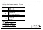
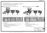
2.  System configuration


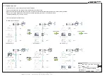
Note 1: Only one outdoor unit can be connected to the AHU interface. 

        However, it is possible to connect up to 15 slave interfaces to the master by setting the AHU interface to the master setting. 
        Up to 16 AHU interface × outdoor units can be connected in 1 system including the master. 

Note 2: Remote control and Modbus communication are valid only for the master unit. 
Note 3: Be sure to connect a leakage breaker in leakage category III. 
 

AHU interface configuration


Model 

Contents 

Applications 

AHU-KIT-SP 

Interface controller 

(master/slave) 

Single refrigerant system. 

Multiple refrigerant system (cascade control). 

Heat exchanger sensor 

Obtain the heat exchanger temperature information. 

Those sensors must be connected each interfaces. 

Return air sensor 

Obtain the return air temperature information. 

This sensor must be connected with master interface. 

Reserve sensor 

Reserve. 


AHU equipment (heat exchanger, fan, total heat exchanger, etc.) be should be procured on site. 


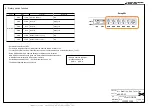
Remote control 

  The remote controller shown in the table below can be connected. 


Model

Contents

Applications

RC-EX3A

Remote control

Connection is optional.

RC-E5

Necessary when Temperature Control is used as a control method.


※   :

Leakage breaker

Fan

AHU

AHU

Controller

AHU interface

Master

Remote 

controller

Modbus

Master

AHU interface

Slave

Slave

Slave

Heat exchanger

Heat exchanger sensor

Return air  

sensor

Single 

outdoor 

unit

Single 

outdoor 

unit

Single 

outdoor 

unit

Analog input

Digital input

Digital output

E

X0

E

X0

E

E

X5

X1

CNH

X2 X3 X4

C

N

N

C

N

N

AHU interface

Slave

C

N

N

X0

Heat exchanger sensor

Heat 
exchanger 
sensor

X7

X7

X7

Содержание AHU-KIT-SP

Страница 1: ... 3 Function 6 4 Rotary switch function 8 5 DIP switch function 9 6 Short PIN function 10 7 Input output circuit 11 7 1 Input circuit 12 7 2 Output circuit 16 7 3 Input output circuit 16 8 Cascade control 17 9 Rotation control 18 10 Fault backup control 19 11 Modbus communication 20 12 Protection control 32 13 Error display 34 14 Installation work 35 15 Wiring procedure 37 16 External dimensions 38...

Страница 2: ...nt Temperature 20 70 Relative humidity 40 90 RH without condensation Power supply Single phase 220 240V 10 15 50Hz Single phase 220V 10 15 60Hz Power consumption 5W Product dimensions height width depth 109 5 mm 290 mm 57 mm Weight 0 55 kg Installation DIN rail TS 35 mm 7 5 mm separate DIN rail required Cascade connection Max 16 outdoor units can be combined by cascade control 16 interfaces are re...

Страница 3: ...rol Heat exchanger sensor Obtain the heat exchanger temperature information Those sensors must be connected each interfaces Return air sensor Obtain the return air temperature information This sensor must be connected with master interface Reserve sensor Reserve AHU equipment heat exchanger fan total heat exchanger etc be should be procured on site Remote control The remote controller shown in the...

Страница 4: ... Control or Temperature Control Select the suitable control combination No 1 No 4 based on the equipment to be installed Correct Master Slave settings are required when using cascading control Check each setting by referring to table 1 1 1 2 in this section Capacity Control SW7 4 OFF External input 0 10V 4 20mA 0 100 System diagram The following control combinations are to be used for Capacity Con...

Страница 5: ...efrigerants The range of use for air conditions conforms to the specifications of the outdoor unit Refer to the technical manual for the outdoor unit Min Max m3 h m3 min SRC40 0 3 0 8 420 7 SRC50 0 3 0 9 420 7 SRC60 0 5 1 1 480 8 FDC71 0 7 1 6 600 10 FDC100 0 7 2 1 840 14 FDC125 1 0 2 2 960 16 FDC140 1 0 2 8 1080 18 FDC200 1 2 4 2 1680 28 FDC250 2 0 4 4 1920 32 FDC280 2 0 4 4 2160 36 Outdoor unit ...

Страница 6: ...e bps ON 9600bps OFF 19200bps 3 Modbus parity ON non parity 2 stop bit OFF even parity 1 stop bit 4 Compressor control ON Temperature Control OFF Capacity Control 1 ON cooling heating OFF run stop 2 Always OFF 3 Always OFF 4 Always OFF 3P 1 2 short not available 2 3 short available 100Ω 3P 1 2 short 0 10V 2 3 short 4 20mA 3P Always 2 3 short Reserve Reserve Reserve DipSW Black Black Reserve Reserv...

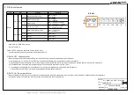
Страница 7: ...V 0 5A X2 4 reserve Power supply AC24 240V DC20 130V 0 5A X2 5 common Common terminal X4a 2P Outdoor unit interface error Voltage free at contact output X4b 2P Compressor ON Voltage free at contact output X4c 2P Defrost ON Voltage free at contact output X4d 2P Voltage free at contact output X4d is selectable by Modbus communication LED1 Normal Green LED2 Error Red X1 2P Remote control Green Remote...

Страница 8: ...SW5 RotarySW Contents Set master and slave by SW1 For a single refrigerant system always set the address of AHU interface to 0 For cascade control set the master address to 0 and the slave address to a value other than 0 1 to F Rotary SW5 and SW6 are address settings for Modbus communication SW5 is Modbus address ones place and SW6 is Modbus address tens place In Modbus communication AHU interface...

Страница 9: ...OFF Capacity Control When capacity control is set default setting the required capacity is directly commanded to the compressor In the following way 0 to 100 of the outdoor unit compressor capacity can be specified as the required capacity Depending on the input voltage 0 10 V or input current 4 20 mA from the analog input the corresponding required capacity is sent to the outdoor unit With Modbus...

Страница 10: ...termination switching Analog input switching Reserve JX1 JX2 JX3 By switching the short PIN on the interface the function on the circuit can be switched JX1 switches the terminal resistor of the Modbus communication circuit JX2 switches the function of the analog input circuit The JX3 is a reserve Do not change from initial setting 2 3 short PWB of AHU interface JX1 Termination available not avail...

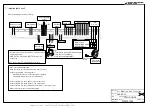
Страница 11: ...e 100 Ω 3 1 Enclosure plate 2 N 1 3 1 N X1 remote control X5 Modus can be used for only master unit CNN Thi R1 2 3 and CNH Thi A must be connected See the 21 AHU T 393 manual for details X0 5 4 3 2 1 7 Input output circuit Refer to the diagram below for wiring X0 1 is the functional ground Wrap the ferrite core included around 6 turns 5 loops Connect to the plate of the enclosure Wire diameter 0 7...

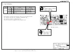
Страница 12: ...pose Input circuit Mounting guidelines for sensors Mounting position of the sensor example Installing temperature sensors Correctly securing temperature sensors Example When installing the temperature sensors make sure that they have optimum contact with the surface to be measured Secure with a wide band hose clamp Important Using cable ties will lead to faulty and squashed temperature sensors Use...

Страница 13: ...Air Handling Unit Interface AHU KIT SP MORIKAWA SPECIFICATION PSZ000Z308 13 38 MODEL NAME MODEL TYPE ISSUE CLASSIFICATION DWG NO REV MARK PAGE 21 09 17 ...

Страница 14: ...Air Handling Unit Interface AHU KIT SP MORIKAWA SPECIFICATION PSZ000Z308 14 38 MODEL NAME MODEL TYPE ISSUE CLASSIFICATION DWG NO REV MARK PAGE 21 09 17 ...

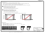
Страница 15: ...uired capacity of 0 100 Please note that there is a dead band in certain ranges ex When 0 5V is input it would be regarded as 0 required capacity 4 20mA Capacity Control SW7 1 ON and JX2 2 3 short 4 20mA signal is regarded as a required capacity of 0 100 Please note that there is a dead band in certain ranges ex When 0 9V is input it would be regarded as 0 required capacity The analog input signal...

Страница 16: ...output circuit The LED output shows the normal abnormal status of the system LED 1 green blinks at 0 5 sec intervals during normal operation LED 2 red flashes when abnormal lights out when normal The number of flashes changes depending on the error status For details refer to 13 error display Input output circuit Input output functions are as follows Item Connector Housing X1 2P Remote control X5 ...

Страница 17: ...nit per AHU interface Run stop operation mode and thermo ON OFF are all judged by master Slave only receives commands from master In cascade control rotation control and fault backup control are automatically enabled Capacity distribution of cascade control The master commands the capacity to each slave The image is shown below Each slave operates according to the master command The master calcula...

Страница 18: ...lly enabled This control averages the compressor accumulated time of all outdoor units When the outdoor unit starts operating the outdoor unit with the lowest compressor accumulated time is preferentially operated When 12 hours have elapsed since the outdoor unit started operating the outdoor unit will be switched Operation switching time 12 hours is fixed This is an example of rotation control Ro...

Страница 19: ...ult backup control In cascade control fault backup control is automatically enabled When an abnormality occurs in an outdoor unit during operation another outdoor unit automatically starts operating Even if the outdoor unit that stopped abnormally is restored the operation of the outdoor unit does not change An example of fault backup control is shown below ...

Страница 20: ... 01 Combinations Transmission speed Parity stop bit Connection RS 485 communication Modbus can monitor the status of the AHU interface and outdoor units Modbus can also change some settings Modbus function The function codes are as follows Function name Remarks 3 0x03 Read holding register Read the contents of the holding register 4 0x04 Read input register Read the contents of the input register ...

Страница 21: ...dress 8 bit Function Function code 8 bit Data Respons data Variable Error check CRC error check 16 bit Overview of Modbus communication The time from the completion of the request to the start of the response and the time from the completion of the response to the start of the next request are as shown in the figure below The following table shows the data length of the request frame The data leng...

Страница 22: ...0 Remote 1 Center Remote 2 Center 0 Emergency stop release 1 Emergency stop 30007 Return air temperature Master 0 32768 32767 0 1 count 30008 External temperature Master 640 32768 32767 0 1 count 30009 Request capacity 0 0 65535 1 count X_all 0 0 1 0 30006 Emergency stop display 0 65535 30004 Center Remote display 0 65535 30001 System Run Stop display 0 65535 30002 Operation mode display 0 65535 D...

Страница 23: ...ty 1Stop bit 1 Non parity 2Stop bit 0 Capacity control 1 Temperature control 30024 SW8 1 Setting display 0 65535 0 Run Stop 1 Cooling Heating 30025 SW8 2 Setting display 0 65535 0 30026 SW8 3 Setting display 0 65535 0 30027 Reserve 0 65535 Reserve 30028 SW7 1 Reading value 0 65535 0 OFF 1 ON 30029 SW7 2 Reading value 0 65535 0 OFF 1 ON 30030 SW7 3 Reading value 0 65535 0 OFF 1 ON 30031 SW7 4 Readi...

Страница 24: ...6 Capacity command Master 0 0 65535 1 count 0 100 31017 Capacity command Slave1 0 0 65535 1 count 0 100 31018 Capacity command Slave2 0 0 65535 1 count 0 100 31019 Capacity command Slave3 0 0 65535 1 count 0 100 31020 Capacity command Slave4 0 0 65535 1 count 0 100 31021 Capacity command Slave5 0 0 65535 1 count 0 100 31022 Capacity command Slave6 0 0 65535 1 count 0 100 31023 Capacity command Sla...

Страница 25: ...ted time Slave11 0 0 65535 1 H count 31044 Compressor accumulated time Slave12 0 0 65535 1 H count 31045 Compressor accumulated time Slave13 0 0 65535 1 H count 31046 Compressor accumulated time Slave14 0 0 65535 1 H count 31047 Compressor accumulated time Slave15 0 0 65535 1 H count 31048 Error code display Master 0 0 65535 0 99 31049 Error code display Slave1 0 0 65535 0 99 31050 Error code disp...

Страница 26: ...67 0 1 count 31078 Heat exchanger temperature Thi R3 Slave4 3276 32768 32767 0 1 count 31079 Heat exchanger temperature Thi R1 Slave5 3276 32768 32767 0 1 count 31080 Heat exchanger temperature Thi R2 Slave5 3276 32768 32767 0 1 count 31081 Heat exchanger temperature Thi R3 Slave5 3276 32768 32767 0 1 count 31082 Heat exchanger temperature Thi R1 Slave6 3276 32768 32767 0 1 count 31083 Heat exchan...

Страница 27: ...32768 32767 0 1 count 31109 Heat exchanger temperature Thi R1 Slave15 3276 32768 32767 0 1 count 31110 Heat exchanger temperature Thi R2 Slave15 3276 32768 32767 0 1 count 31111 Heat exchanger temperature Thi R3 Slave15 3276 32768 32767 0 1 count 31112 Compressor Hz display Master 0 0 65535 1 Hz count 0 120Hz 31113 Compressor Hz display Slave1 0 0 65535 1 Hz count 0 120Hz 31114 Compressor Hz displ...

Страница 28: ...e13 0 0 65535 0 Normal 1 Defrost 31142 Defrost display Slave14 0 0 65535 0 Normal 1 Defrost 31143 Defrost display Slave15 0 0 65535 0 Normal 1 Defrost 31144 Oil return display Master 0 0 65535 0 Normal 1 Oil return 31145 Oil return display Slave1 0 0 65535 0 Normal 1 Oil return 31146 Oil return display Slave2 0 0 65535 0 Normal 1 Oil return 31147 Oil return display Slave3 0 0 65535 0 Normal 1 Oil ...

Страница 29: ...Slave5 0 0 65535 0 Normal 1 Abnormal stop 31166 Abnormal stop status display Slave6 0 0 65535 0 Normal 1 Abnormal stop 31167 Abnormal stop status display Slave7 0 0 65535 0 Normal 1 Abnormal stop 31168 Abnormal stop status display Slave8 0 0 65535 0 Normal 1 Abnormal stop 31169 Abnormal stop status display Slave9 0 0 65535 0 Normal 1 Abnormal stop 31170 Abnormal stop status display Slave10 0 0 655...

Страница 30: ... run 0 cooling 1 heating 40003 Set temperature command 46 23 36 60 0 5 count 36 18 60 30 0 emergency stop release 1 emergency stop 40006 CPU reset command 0 0 1 0 NOP 1 reset Compressor accumulated time all reset command 0 100 40005 0 0 1 40007 0 0 1 40001 Emergency stop command Capacity Control command Run stop command 0 0 1 40002 Operation mode command 0 0 1 0 NOP 1 reset 40008 0 0 10000 0 01 co...

Страница 31: ...ccumulated time reset command slave 8 Compressor accumulated time reset command slave 9 Compressor accumulated time reset command slave 10 Compressor accumulated time reset command slave 11 Compressor accumulated time reset command slave 12 Compressor accumulated time reset command slave 13 Compressor accumulated time reset command slave 14 Compressor accumulated time reset command slave 15 41016 ...

Страница 32: ... operation timer Compressor will not stop for 3 minutes after the compressor ON However it stops immediately when the unit is stopped by means of the ON OFF switch or when the thermostat is turned OFF by the change of operation mode Cooling frost protection To prevent frosting during cooling mode operation the compressor OFF if the AHU heat exchanger temperature detected with Thi R drops to 1 0 or...

Страница 33: ...o stop the fan motor on the AHU side However if the fan motor cannot be stopped under the conditions of use of the air handling unit fan operation can be continued during defrosting and oil return only if the following conditions are met If the following conditions are not met stop the AHU fan motor during defrosting and oil return signal output Condition Only when the difference in height between...

Страница 34: ...sensor disconnection Resolution of disconnection Once E8 Heating overload error Normalisation of heat exchanger temperature Once E14 Master slave communication error Normal reception of slave signal Three times E63 Emergency stop Emergency stop release Continuous 13 Error display AHU interface detects the following errors To check the error code remote control or Modbus device is required To detec...

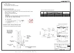
Страница 35: ... 21 09 17 14 Installation work Installation procedure Install AHU interface in the direction shown in the figure below so that letters can be read correctly Installation clearances 1 Slide the fixed part down 2 places 2 Hang the box on the DIN rail 3 Push the fixed part 2 places up and fix onto the DIN rail Make sure it is securely fastened ...

Страница 36: ...Air Handling Unit Interface AHU KIT SP MORIKAWA INSTALLATION PSZ000Z308 36 38 MODEL NAME MODEL TYPE ISSUE CLASSIFICATION DWG NO REV MARK PAGE 21 09 17 Remove the cover ...

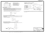
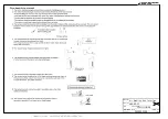
Страница 37: ...ighter than the one specified in parentheses for each type below ordinary tough rubber sheathed cord code designation 60245 IEC 53 Do not use anything lighter than polychloroprene sheathed flexible cord code designation 60245 IEC57 for supply cords of appliances parts for outdoor use Cascade connection X7 signal lines Wire diameter 0 75mm2 1 25mm2 The line length between Master and Slave must be l...

Страница 38: ...Air Handling Unit Interface AHU KIT SP MORIKAWA EXTERNAL DIMENSIONS PSZ000Z308 38 38 MODEL NAME MODEL TYPE ISSUE CLASSIFICATION DWG NO REV MARK PAGE 21 09 17 16 External dimensions ...

Отзывы: