background image

28

SLC Integration - QX-mini and FleX-Net™ - Single Stage

5.2

Wiring

For SLC integration, connect wire from preferred loop of FleX-Net™ to SLC terminal on QX-
mini Master. 

Note:

If the system is comprised of a QX-mini Master and booster panels, 
only the QX-mini Master must be wired with FACP.

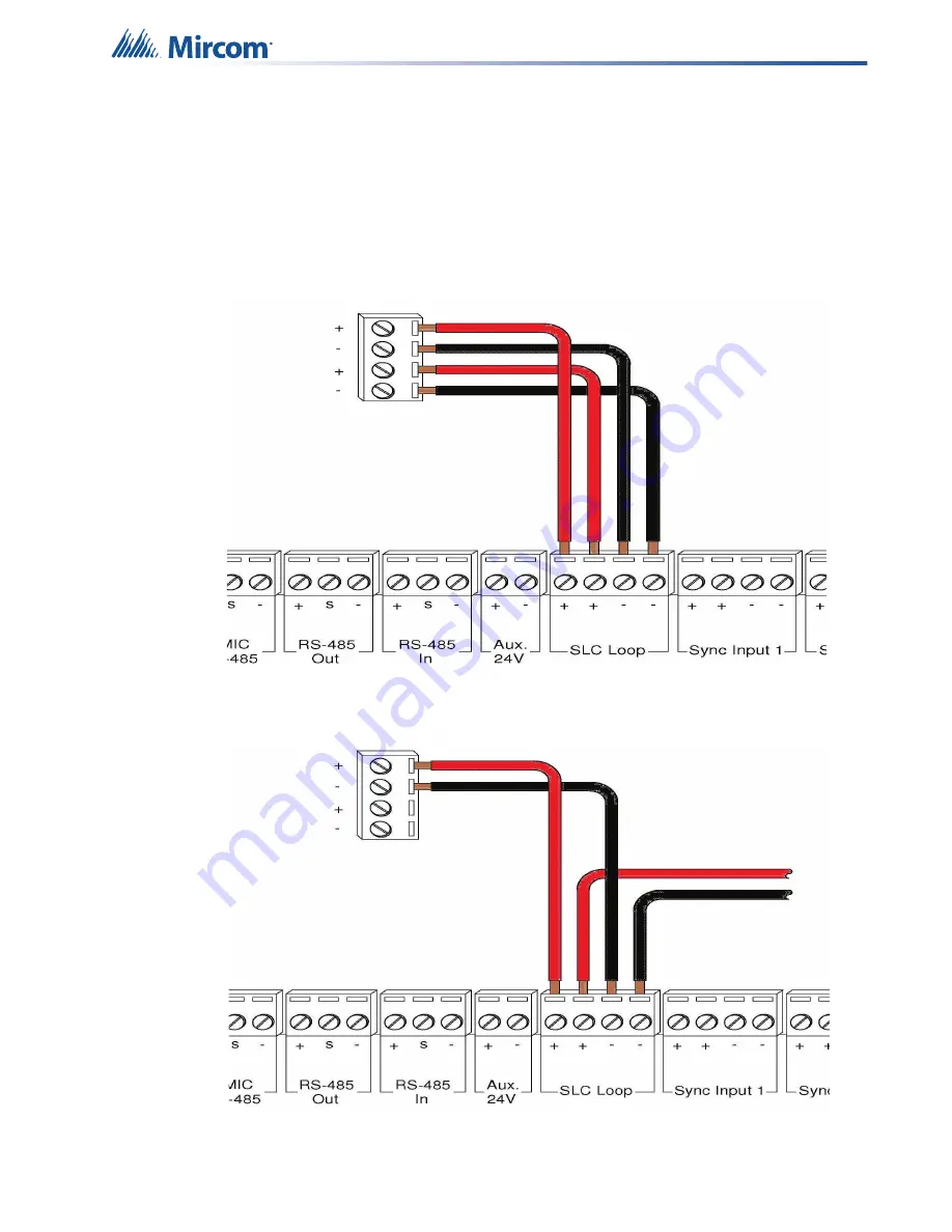
5.2.1 Class A

Figure 41 Class A wiring to connect FACP with QX-mini master via SLC link

5.2.2 Class B

Figure 42 Class B wiring to connect FACP with QX-mini master via SLC link

Содержание QX-mini

Страница 1: ...Programming Guide Emergency and Fire Alarm Audio System LT 2079 Rev 2 July 2019 QX mini...

Страница 2: ......

Страница 3: ...Introduction 19 4 2 Wiring 20 4 3 Configuration Steps 22 4 4 SLC Address Configuration 26 5 0 SLC Integration QX mini and FleX Net Single Stage 27 5 1 Introduction 27 5 2 Wiring 28 5 3 Configuration...

Страница 4: ...wo Stage 66 10 1 Introduction 66 10 2 Wiring 67 10 3 Configuration Steps 69 10 4 SLC Address Configuration 74 11 0 SLC Integration QX mini and FX 2000 Single Stage 75 11 1 Introduction 75 11 2 Wiring...

Страница 5: ...re Alarm Audio System Mircom strives to offer the highest quality products and services To that end we encourage you to contact us with any inquiries feedback or assistance you may require If you have...

Страница 6: ...In order to add booster panels click Add under Panels Figure 2 New Job window 4 In the Pre Tone Setting box select the kind of pre tone or No Tone If a pre tone is selected then the QX mini automatic...

Страница 7: ...can be selected as per requirements Figure 3 Edit Job window Note NAC s enabled during All Call feature allows strobes to flash while paging If strobes are not required to flash during all call this...

Страница 8: ...available when None has been selected as SLC type Figure 5 Monitoring 9 If NACs on FACP need to be in sync with NACs on QX mini select appropriate stage strobe protocol and select Follow Sync Input 10...

Страница 9: ...nel Inputs After zones are correlated to desired outputs they can be assigned to SLC addresses relay inputs or sync inputs for activation 2 2 1 Relay Sync Input Correlation 1 Click on panel inputs cli...

Страница 10: ...nel inputs click on the sign Select Panel input address to activate EVAC zone Ensure this address corresponds to supervised output module in the FACP job Figure 9 SLC RELAY IN SYNC Correlations 2 3 Co...

Страница 11: ...from existing library in the configurator by clicking Add Figure 11 Audio Messages 3 Select audio clips from the library on the left and compose a message Clips can be imported recorded and created u...

Страница 12: ...ected from the drop down as shown below For any other messages manual must be selected Figure 13 Alert Stage 5 Messages can be assigned to switches by using left click on the mouse keeping it pressed...

Страница 13: ...the zone to the appropriate switch 2 4 Saving a Job 1 Click Save Job The Configurator does not automatically save the job Figure 16 Save Job button 2 5 Connecting to a Panel 1 Use the USB connector to...

Страница 14: ...nd is complete and connection is automatically disconnected Figure 20 Please wait 30 seconds while the panel reboots 3 After job has been successfully sent to panel connection will be lost Disconnect...

Страница 15: ...e the backup amplifier as shown in LT 2077 QX mini Installation Manual To enable a backup amplifier 1 In the Edit Job window click Master Panel 0 then click Edit 2 Click Next 3 In the Amplifiers windo...

Страница 16: ...16 Working with the Configurator 4 Select Backup Figure 22 Configure a backup amplifier 5 Click OK...

Страница 17: ...ect to the panel and then click Firmware Upgrade Figure 23 Firmware Upgrade 3 Choose the latest firmware from the list and click upgrade If firmware file is saved on the computer click on Custom Firmw...

Страница 18: ...the firmware version by clicking Firmware Upgrade The now current version is displayed at the bottom of the window Figure 26 List of firmwares Note ECS configurator has audible notification feature wh...

Страница 19: ...on The QX mini is designed to interface with Mircom FACPs over an SLC link where it is seen as a number of virtual devices This single link allows for zone by zone automatic control as well as specifi...

Страница 20: ...system is comprised of a QX mini Master and booster panels only the QX mini Master must be wired with FACP 4 2 1 SLC Class A Figure 28 Class A wiring to connect FACP with QX mini Master via SLC link...

Страница 21: ...SLC Integration QX mini and FleX Net Two Stage 21 diagrams for wiring 4 2 3 SYNC Class A Figure 30 Class A Sync 4 2 4 SYNC Class B Figure 31 Class B Sync...

Страница 22: ...e window below See section 4 4 on page 26 for details Note These devices are integrated in QX mini as virtual devices and do not need to be physically installed on the loop The number of virtual SLC d...

Страница 23: ...job or create a new job 3 Select a unique password that will be assigned to the job specifically 4 Define timing for page inhibit delay as per requirements 5 Select either Class A or Class B depending...

Страница 24: ...on FACP Note Under signal silence three different behaviors can be selected All Speakers Horn Strobes All turns off all the outputs Speakers turns off speaker outputs only and Horn Strobes turns off N...

Страница 25: ...Ensure that stage for Alert and Evac is selected from the drop down box as shown below Figure 37 Audio Clips 13 Click on panel inputs click on the sign Select Panel input address to activate EVAC and...

Страница 26: ...ni Audible and Visual signal silence Configure this as a relay output module address 104 shown in Figure 32 and correlate it to signal silence common status in the FACP configurator Paging Message Act...

Страница 27: ...tion The QX mini is designed to interface with Mircom FACPs over an SLC link where it is seen as a number of virtual devices This single link allows for zone by zone automatic control as well as speci...

Страница 28: ...to SLC terminal on QX mini Master Note If the system is comprised of a QX mini Master and booster panels only the QX mini Master must be wired with FACP 5 2 1 Class A Figure 41 Class A wiring to conne...

Страница 29: ...not need to be physically installed on the loop The number of virtual SLC devices depends on your configuration you can use as many as your job requires Figure 43 The addresses may vary depending on e...

Страница 30: ...one to all trouble input devices as shown below Figure 45 Trouble zone correlations 8 Correlate Monitor zone to all monitor inputs Figure 46 Monitor zone correlations 9 Ensure all the addresses are co...

Страница 31: ...g job or create a new job 3 Select a unique password that will be assigned to the job specifically 4 Define timing for page inhibit delay as per requirements 5 Select either Class A or Class B dependi...

Страница 32: ...er signal silence three different behaviors are available for selection All Speakers Horn Strobes All turns off all the outputs Speakers turns off speaker outputs only and Horn Strobes turns off NACs...

Страница 33: ...ne Ensure this address corresponds to supervised output module in Figure 43 Figure 50 SLC RELAY IN SYNC Correlations 12 All the correlations in job file can be viewed in Report as shown below Figure 5...

Страница 34: ...ports to FACP when QX mini has been manually activated For example when microphone is active or a message has been activated trouble will report back to FACP Configure this as an input module Address...

Страница 35: ...35 6 0 Relay Input QX mini and FleX Net 6 1 Introduction The QX mini is designed to interface with FACPs via relay inputs which provide zone activation functionality Figure 52 QX mini and FleX Net...

Страница 36: ...the wire from a normally open relay contact to relay 1 or relay 2 terminal on the QX mini Master Note Note If system is comprised of a QX mini Master and booster panels only the QX mini Master must b...

Страница 37: ...window below Note In this particular example relay output module MIX M500R was used to activate the EVAC zone This module must be correlated to all the alarm inputs in the job Figure 54 The addresses...

Страница 38: ...password that will be assigned to the job specifically 4 Define timing for page inhibit delay as per local requirement 5 Select either Class A or Class B depending on the inter panel wiring 6 Click o...

Страница 39: ...in sync with NACs on FACP Figure 57 Follow sync input Note Signal silence cannot be performed via the relay input connection this feature is only available through an SLC connection with a Mircom pan...

Страница 40: ...and create a message Ensure that stage for Evac is selected from the drop down Figure 60 Audio Clips 12 Click on panel inputs click on the sign Select the relay input that has been wired to activate E...

Страница 41: ...t 41 13 All the correlations in job file can be viewed in Report as shown below Figure 62 Report 14 Save the job connect to QX mini and send the job 15 After job has been successfully sent to the pane...

Страница 42: ...on The QX mini is designed to interface with Mircom FACPs over an SLC link where it is seen as a number of virtual devices This single link allows for zone by zone automatic control as well as specifi...

Страница 43: ...nnect wire from preferred loop of FX 3500 to SLC terminal on QX mini Master Note If the system is comprised of a QX mini Master and booster panels only the QX mini Master must be wired with FACP 7 2 1...

Страница 44: ...00 Two Stage 7 2 2 Class B Figure 65 Class B wiring to connect FACP with QX mini Master via SLC link Note If QX mini system is required to follow sync from FACP refer to below diagrams for wiring 7 3...

Страница 45: ...SLC Integration QX mini and FX 3500 Two Stage 45 7 4 SYNC CLASS B Figure 67 Sync Class B...

Страница 46: ...3 Click on the loop that has been wired to SLC terminal on QX mini Master Ensure there is enough space to configure virtual devices on that loop 4 Configure the loop as shown in the window below See...

Страница 47: ...ts 5 Select either Class A or Class B depending on the inter panel wiring 6 Click on New Job or Edit Job for an existing file and choose the SLC Type Series FX 3500 FX 2000 FleX Net MR 3500 Figure 70...

Страница 48: ...ion All Speakers Horn Strobes All turns off all the outputs Speakers turns off speaker outputs only and Horn Strobes turns off NAC s when signal silence on FACP is pressed 9 If NAC s on FACP need to b...

Страница 49: ...age 49 11 Click on Edit Audio Figure 73 Edit Audio button 12 Click Add and create an alert and evac message based on the requirements Ensure that stage for Alert and Evac is selected from the drop dow...

Страница 50: ...ure 75 SLC RELAY IN SYNC Correlations 14 In order to see Page Inhibit countdown the feature can be assigned to one of the zone switches Right click on the switch and select Assign paging inhibit Flash...

Страница 51: ...n QX mini has been manually activated For example when microphone is active or a message has been activated trouble will report back to FACP Configure this as an input module Address 205 in Figure 69...

Страница 52: ...tion The QX mini is designed to interface with Mircom FACPs over an SLC link where it is seen as a number of virtual devices This single link allows for zone by zone automatic control as well as speci...

Страница 53: ...onnect wire from preferred loop of FX 3500 to SLC terminal on QX mini Master Note If the system is comprised of a QX mini Master and booster panels only the QX mini Master must be wired with FACP 8 2...

Страница 54: ...54 SLC Integration QX mini and FX 3500 Single Stage 8 2 2 Class B Figure 79 Class B wiring to connect FACP with QX mini Master via SLC link...

Страница 55: ...important to change AP Start to enable CLIP devices on the loop 3 Click on the loop that has been wired to SLC terminal on QX mini Master Ensure there is enough space for at least seven devices on tha...

Страница 56: ...ocal requirements 5 Select either Class A or Class B depending on the inter panel wiring 6 Click on New Job or Edit Job for an existing file and choose the SLC Type Series FX 3500 FX 2000 FleX Net MR...

Страница 57: ...ions can be selected All Speakers Horn Strobes All turns off all the outputs Speakers turns off speaker outputs only and Horn Strobes turns off NACs when signal silence on FACP is pressed 9 If NACs on...

Страница 58: ...nsure this address corresponds to supervised output module in Figure 81 Figure 85 SLC RELAY IN SYNC Correlations 12 All the correlations in job file can be viewed in Report as shown below Figure 86 Re...

Страница 59: ...en QX mini has been manually activated For example when microphone is active or a message has been activated trouble will report back to FACP Configure this as an input module Address 205 in Figure 81...

Страница 60: ...60 9 0 Relay Input QX mini and FX 3500 9 1 Introduction The QX mini is designed to interface with FACPs via relay inputs which provide zone activation functionality Figure 87 QX mini and FX 3500...

Страница 61: ...ct the wire from a normally open relay contact to relay 1 or relay 2 terminal on the QX mini Master Note If system is comprised of a QX mini Master and booster panels only the QX mini Master must be w...

Страница 62: ...ay vary based on different applications 3 Click on the loop that has been wired to SLC terminal on the QX mini Master 4 Configure the loop as shown in the window below Note In this particular example...

Страница 63: ...local requirement 5 Select either Class A or Class B depending on the inter panel wiring 6 Click on New Job or Edit Job for an existing file and choose None under SLC type Figure 90 New Job window 7 C...

Страница 64: ...rough an SLC connection with a Mircom panel using addressable modules 9 Create zones as per requirement and correlate them to NACs and speaker outputs Figure 92 Create zones 10 Click on Edit Audio Fig...

Страница 65: ...has been wired to activate EVAC zone Figure 95 SLC RELAY IN SYNC Correlations 13 All the correlations in job file can be viewed in Report as shown below Figure 96 Report 14 Save the job connect to QX...

Страница 66: ...ion The QX mini is designed to interface with Mircom FACPs over an SLC link where it is seen as a number of virtual devices This single link allows for zone by zone automatic control as well as specif...

Страница 67: ...C terminal on QX mini Master Note If system is comprised of a QX mini Master and booster panels only the QX mini Master must be wired with FACP 10 2 1 SLC Class A Figure 98 Class A wiring to connect F...

Страница 68: ...on QX mini and FX 2000 Two Stage Note If QX mini system is required to follow sync from FACP refer to below diagrams for wiring 10 2 3 SYNC Class A Figure 100 Sync Class A 10 2 4 SYNC Class B Figure 1...

Страница 69: ...ough space for at least seven devices on that loop 4 Configure the loop as shown in the window below See section 10 4 on page 74 for details Note These devices are integrated in QX mini as virtual dev...

Страница 70: ...job or create a new job 3 Select a unique password that will be assigned to the job specifically 4 Define timing for page inhibit delay as per requirements 5 Select either Class A or Class B depending...

Страница 71: ...ACP Note Under signal silence three different behaviors are available for selection All Speakers Horn Strobes All turns off all the outputs Speakers turns off speaker outputs only and Horn Strobes tur...

Страница 72: ...Stage 11 Click on Edit Audio Figure 106 Edit Audio button 12 Click Add and create an alert and evac message based on the requirements Ensure that stage for Alert and Evac is selected from the drop dow...

Страница 73: ...re 108 SLC RELAY IN SYNC Correlations 14 In order to see Page Inhibit countdown the feature can be assigned to one of the zone switches Right click on the switch and select Assign paging inhibit Flash...

Страница 74: ...e when microphone is active or a message has been activated trouble will report back to FACP Configure this as an input module Address 101 in Figure 102 in the FACP configurator and select type as bui...

Страница 75: ...tion The QX mini is designed to interface with Mircom FACPs over an SLC link where it is seen as a number of virtual devices This single link allows for zone by zone automatic control as well as speci...

Страница 76: ...SLC terminal on QX mini Master Note If the system is comprised of a QX mini Master and booster panels only the QX mini Master must be wired with FACP 11 2 1 Class A Figure 111 Class A wiring to conne...

Страница 77: ...devices on that loop 4 Configure the loop as shown in the window below See section 11 4 on page 81 for details Note These devices are integrated in QX mini as virtual devices and do not need to be ph...

Страница 78: ...job or create a new job 3 Select a unique password that will be assigned to the job specifically 4 Define timing for page inhibit delay as per requirements 5 Select either Class A or Class B dependin...

Страница 79: ...er signal silence three different behaviors are available for selection All Speakers Horn Strobes All turns off all the outputs Speakers turns off speaker outputs only and Horn Strobes turns off NACs...

Страница 80: ...Ensure this address corresponds to supervised output module in Figure 113 Figure 117 SLC RELAY IN SYNC Correlations 12 All the correlations in job file can be viewed in Report as shown below Figure 1...

Страница 81: ...For example when microphone is active or a message has been activated trouble will report back to FACP Configure this as an input module Address 105 in Figure 113 in the FACP configurator and select...

Страница 82: ...82 12 0 Relay Input QX mini and FX 2000 12 1 Introduction The QX mini is designed to interface with FACPs via relay inputs which provide zone activation functionality Figure 119 QX mini and FX 2000...

Страница 83: ...ct the wire from a normally open relay contact to relay 1 or relay 2 terminal on the QX mini Master Note If system is comprised of a QX mini Master and booster panels only the QX mini Master must be w...

Страница 84: ...SLC terminal on QX mini Master 4 Configure the loop as shown in the window below Note In this example relay output module MIX M500R was used to activate the EVAC zone This module must be correlated to...

Страница 85: ...password that will be assigned to the job specifically 4 Define timing for page inhibit delay as per local requirement 5 Select either Class A or Class B depending on the inter panel wiring 6 Click on...

Страница 86: ...n sync with NACs on FACP Figure 123 Follow Sync Input Note Signal silence cannot be performed via the relay input connection this feature is only available through an SLC connection with a Mircom pane...

Страница 87: ...reate a message Ensure that stage for Evac is selected from the drop down Figure 126 Audio Clips 12 Click on panel inputs by clicking on the sign Select the relay input that has been wired to activate...

Страница 88: ...000 13 All the correlations in job file can be viewed in Report as shown below Figure 128 Report 14 Save the job connect to QX mini and send the job 15 After job has been successfully sent to the pane...

Страница 89: ...larm signal and the other amplifier provides the alert signal The splitter splits the outputs from the amplifiers into 8 outputs 1 output for each floor In this way the system provides an alarm signal...

Страница 90: ...Zones and Correlate them to Master Splitter Outputs Add Inputs for Splitter Outputs Create Messages Assign Zones and Messages to Inputs Details on how to perform these steps are in the following page...

Страница 91: ...utput modules that will activate functions on the QX mini and input modules that will listen for reporting from the QX mini See section 13 4 for details on the reporting functions Table 1 shows an exa...

Страница 92: ...Signal Floor 2 Alert Detectors on floors 1 to 8 Fire Drill Total Evacuation 283 183 Supervised Output Module CLIP Signal Floor 3 Alert Detectors on floors 1 to 8 Fire Drill Total Evacuation 284 184 Su...

Страница 93: ...floors 3 4 and 5 Total Evacuation 295 195 Relay Output Module CLIP Relay Floor 5 Evac Detectors on floors 4 5 and 6 Total Evacuation 296 196 Relay Output Module CLIP Relay Floor 6 Evac Detectors on f...

Страница 94: ...ther Class A or Class B 6 Under SLC Type select Series FX 3500 FX 2000 FleX Net MR 3500 Figure 134 New Job window 7 Click Master Panel 0 and then click Edit The Panel Wizard opens 8 In the Panel Wizar...

Страница 95: ...and strobe protocol and select Follow Sync Input Create Zones and Correlate them to Master Splitter Outputs 1 In the Panel Wizard click Next until the window shown in Figure 136 appears 2 Create zone...

Страница 96: ...Floor 6 Alert Master Splitter Output 6 Master Amplifier Output 1 Floor 7 Alert Master Splitter Output 7 Master Amplifier Output 1 Floor 8 Alert Master Splitter Output 8 Master Amplifier Output 1 Floor...

Страница 97: ...output that acts as an input to this zone then click OK Figure 138 Select Master Amplifier Output 1 3 Do the same for the other zones In the example shown in Table 2 Master Amplifier Output 1 serves a...

Страница 98: ...window appears Figure 142 2 Click the button Select the panel input addresses to activate the evacuation and alert zones Ensure that the addresses correspond to the modules in the FACP configuration...

Страница 99: ...Evacuation Message 194 Floor 4 Evac Evacuation Message 195 Floor 5 Evac Evacuation Message 196 Floor 6 Evac Evacuation Message 197 Floor 7 Evac Evacuation Message 198 Floor 8 Evac Evacuation Message 1...

Страница 100: ...nfigurator Paging Message Active This feature reports to the FACP when the QX mini has been manually activated For example when the microphone is active or a message has been activated a trouble is re...

Страница 101: ...without prior notice www mircom com CANADA Main Office 25 Interchange Way Vaughan ON L4K 5W3 Tel 905 660 4655 888 660 4655 Fax 905 660 4113 U S A 4575 Witmer Industrial Estates Niagara Falls NY 14305...

Отзывы: