background image

QIF-5000B Configuration Download procedure:


1.  Remove the connections J1 and J2 to the paging module (QMP-5100B or QMP-5101B) on the QIF-5000B 

board. 

2.  Move the CONFIG jumper, JP5 on the QIF-5000B board to the program enable position between pins 1 and 

2.  Press the QX-5000 System Reset button on the QIF-5000B, located just below the CONFIG jumper.   Wait 
until the green A.C. ON LED starts flashing. 

3.  Connect the RS-485 IMA or UIMA to the computer.  Connect the ribbon cable end to J9 of the QIF-5000B. 
4.  Launch application, ‘Audio Configuration Utility’ from the P.C. 


5.  Proceed with Audio Cabinet Configuration (zone mapping) according to the QX-5000 installation manual and 

Audio Configuration Utility Manual (Document # LT-9028).  

6.  Follow section ‘QDV-1000 Configuration’ in LT-9028 to configure the QDV-1000 settings. 
 

IMPORTANT

:  

o

  Every installed chip should have a message programmed on its channelX line (X =01 to 04).  If 

channel 04 (ALERT2) is used for manual messages only, one of the message must be selected and 
programmed on channel 04 line with part1 repeat set at ‘255' and repeat all set at ‘255'.   

o

  Message 1 cannot be used to build the play back message. 

o

  For Mass Code operation, see below. 


7.  From the main system window, under the ‘System’ pane, verified that the option ‘QDV Installed: Yes’ is 

present. 

Once all elements of the audio system have been configured.  From the tool bar, hit the ‘send’ button to send 
the configuration to the QIF-5000B. 

9.  Noted that the ‘AC On’ green LED stop flashing and then turns back on solidly, this indicates that the 

configuration has been send successfully. 

10.  Replace jumper JP5 back to its normal position. 


Additional note for QX-5000 system with QDV-1000 and Silenceable speaker 
option: 

 
When Silenciable speakers are used, the QX-5000 audio system has to play the ‘Pre-announce Tone’ before the 
alarm signal.  This is to re-sound any previously silenced speakers.  To enable the QX-5000 system for this feature, 
the ‘Alert 2' I.C. must be installed in U5 socket.  The ‘Pre-announce’ tone is also required to be recorded onto the Alert 
2 channel.  
 
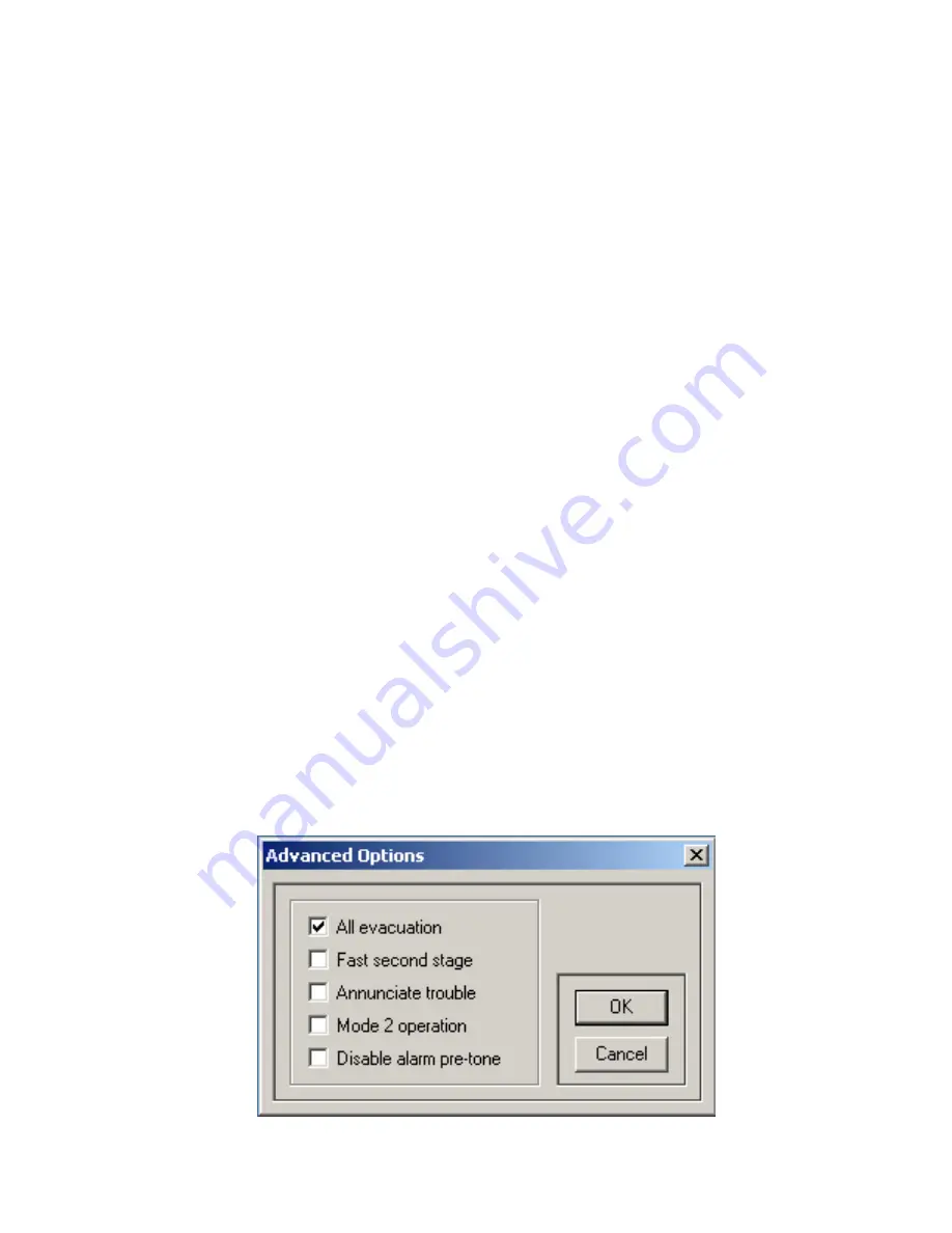
In the Audio Configuration Utility, under the ‘System Configuration’ > ‘Advance Options’ window, verify that the option 
box ‘Disable alarm pre-tone’ is not selected.


LT-901 Rev.4 Aug 2006 

          Page 7 of 10 

Содержание QDV-1000

Страница 1: ...p Beep Beep Channel 2 Message 1 For internal use only do not use 2 Temporal Tone Channel 2 Message 2 3 Boston Message Attention please the signal tone you have just heard indicated a report of an emer...

Страница 2: ...ntegrated circuit chip into socket U3 this is the standard operation set up 4 For voice recording to be played on the Alert channel 3 install a QDV 0001 integrated circuit chip socket into U4 5 For vo...

Страница 3: ...Windows Media Player or Windows Sound Recorder 2 The sound clip files to be recorded 3 Sound clip file SO 195 wav the 5 seconds of pre announcement tone LT 901 Rev 4 Aug 2006 Page 3 of 10 Procedure S...

Страница 4: ...channel number and the new message number 4 Press the REC button on the QDVP 100 to start recording and play the message from the computer Press the STOP to end the recording 5 Play back the recorded...

Страница 5: ...ed for alarm messages Special tone file SO 195 wav must be used 2 If Massachusetts Boston code signaling is used the evacuation tone SO 181 wav must be programmed in message position 2 of evacuation c...

Страница 6: ...r 2 Locate the J8 header on the QIF 5000B Align the key on the ribbon cable header from QDV 1000 J2 with the opening of the J8 and plug the cable into the shrouded header 3 Connect a wire from termina...

Страница 7: ...4 line with part1 repeat set at 255 and repeat all set at 255 o Message 1 cannot be used to build the play back message o For Mass Code operation see below 7 From the main system window under the Syst...

Страница 8: ...re the QDV 1000 Channel 4 as show in the diagram below Also note that the Message of Part 2 is the message number of the Pre announce tone SO 195 wav recorded in Alert2 I C LT 901 Rev 4 Aug 2006 Page...

Страница 9: ...d up do the following 1 Set the rotary switches on the QIF 5000B to 97 2 Move the jumper JP5 on the QIF 5000B to position 1 and 2 3 Press on the reset switch on the QIF 5000B 4 Wait for the green LED...

Страница 10: ...onfiguration data to the QIF 5000B and wait until download completes 11 Once LED goes back to steady green may take 30 45 seconds replace jumper JP5 to position 2 and 3 During all the above operations...

Страница 11: ......

Страница 12: ...5 660 4113 Mircom 2011 Printed in Canada Subject to change without prior notice www mircom com U S A 4575 Witmer Industrial Estates Niagara Falls NY 14305 Tel 888 660 4655 905 660 4655 Fax 905 660 411...

Отзывы: