GUIDE TO INSTALLATION AND OPERATION
AAP-1741 |
15
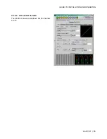
3.3.2.2 CH 9 to CH 16 tabs:
The functions are same as above but for channels 9 to 16.
Страница 1: ...g Audio Processor Guide to Installation and Operation M768 8200 100 6 Jun 2007 Miranda Technologies Inc 3499 Douglas B Floreani St Laurent Qu bec Canada H4S 1Y6 Tel 514 333 1772 Fax 514 333 9828 www m...
Страница 2: ...do so Refer all servicing to qualified service personnel Servicing should be done in a static free environment Electromagnetic Compatibility This equipment has been tested for verification of complian...
Страница 3: ...Rear Panel Options 4 3 Operation 5 3 1 Control options 5 3 2 Local control using the Densit frame control panel 5 3 2 1 Status LED 6 3 2 2 Menu for local control 7 3 3 Remote control using iControl 10...
Страница 4: ...GUIDE TO INSTALLATION AND OPERATION AAP 1741...
Страница 5: ...o bus the AAP 1741 provides processing for 8 channels originating from a video card Once processed the signals are sent back to be embedded and are also available at the analog outputs Along with the...
Страница 6: ...rter Stand alone or associated with an FRS 1xxx as an audio processor with analog inputs and outputs 1 4 Functional Block diagram Remote Control Select Status L1 Monitor OUT Analog Inputs R1 L2 R2 8 1...
Страница 7: ...GUIDE TO INSTALLATION AND OPERATION AAP 1741 3 1 5 Card front edge layout STATU S D 1 SE LE C T SW 1 Select Button Status Led AAP 1741 ABUS connector...
Страница 8: ...r when installing or removing the card When the AAP 1741 is used in conjunction with a video module such as FRS 1101 and or another audio module like AAP 1741 or UAP 1783 the ABUS flat cable must be i...
Страница 9: ...le of displaying two lines of text each 16 characters in length and five pushbuttons The panel is assigned to operate any card in the frame by pushing the SELECT button on the front edge of that card...
Страница 10: ...Serial Report GPI Report Green Yellow Red Flashing Red Flashing Yellow Card system error Not expected reference Error Reference error NSD CH 1 to 4 Analog input NSD CH 9 to 16 Ext CH 1 8 or 9 16 OVERL...
Страница 11: ...CH16 TONE CH1 TONE CH16 DATA TYPE CH1 parameter CH16 parameter parameter PCM NON PCM DOLBY E AC 3 INPUT PROCESSING INPUT PROCESSING LEVEL PHASE INVERT FIXED DELAY COARSE CUT 95 5 1 0 0 5 0 0 5 1 0 12...
Страница 12: ...5 3 0 4 5 6 LFE SURROUND LEVELS DOWNMIX MODE dB OFF UPMIX DOWNMIX OPERATION MODE or dB DOWNMIX SOURCE CH1 CH9 CH16 LtRt LoRo TYPE CONTROL dB CUT 6 4 5 3 1 5 0 1 5 3 0 4 5 6 CUT 6 4 5 3 1 5 0 1 5 3 0 4...
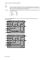
Страница 13: ...D ANALOG IN1 A D ANALOG OUT 1L PROC CH1 PROC CH4 PROC CH9 EXT CH1 9 PROC CH 16 EXT CH8 16 OUT MIXER 1 IN A OUT MIXER 1 IN B OUT MIXER 4 IN A OUT MIXER 4 IN B ANALOG OUT 1L OUTPUT MUTE PROC CH4 ANALOG...
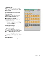
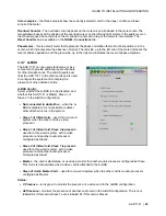
Страница 14: ...eatures of this panel Panel selection buttons The buttons on the left side of the panel are used to select the contents of the right portion of the screen The selected button is highlighted and the ma...
Страница 15: ...tatus Green if OK Yellow if warning detected Red if error detected Grey if detection is disabled Note Each input error can be masked independently 10 Reference status Green if OK Red if an error has b...
Страница 16: ...e the desired level may be input directly a Mute icon button and a Phase Invert checkbox At the bottom are three checkboxes Swap allows channel swapping inside a pair Lock locks both channel sliders t...
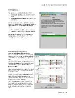
Страница 17: ...d before a signal absence error is reported can be adjusted from 0 to 255 seconds The default value is set to 15 s and an input box is available to enter a numerical value directly 3 3 1 2 Audio Proce...
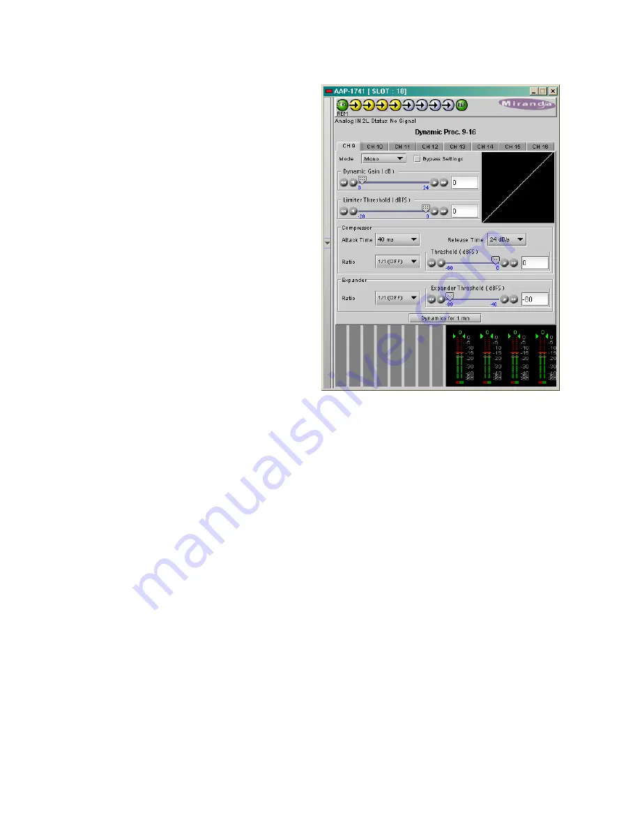
Страница 18: ...rom 0 to 24 dB gain with the slider or a direct keyboard entry The Limiter Threshold is adjusted from 0 to 20 dBFS with the slider or a direct keyboard entry 0 is the default value and corresponds to...
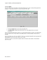
Страница 19: ...GUIDE TO INSTALLATION AND OPERATION AAP 1741 15 3 3 2 2 CH 9 to CH 16 tabs The functions are same as above but for channels 9 to 16...
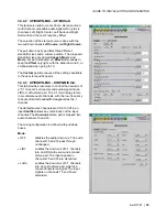
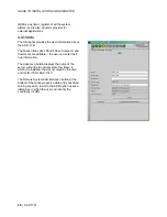
Страница 20: ...card A1 is always Local Slave 1 or Master o A2 selects one of the 16 channels from an audio card A2 is always Slave2 or Slave The output Level is adjustable from 96 to 12 dB with the slider or a direc...
Страница 21: ...f the 16 channels from an audio card A1 is always Local Slave 1 or Master o A2 selects one of the 16 channels from an audio card A2 is always Slave2 or Slave The contribution of each of the sources to...
Страница 22: ...usted down to 0 dBu 3 3 4 UP DOWN MIX 3 3 4 1 UP DOWN MIX Config tab With the UP DOWN MIX option enabled see section 3 3 11 the UP DOWN MIX mode radio buttons offer the choice between OFF UPMIX DOWNMI...
Страница 23: ...eds 3 3 4 3 UP DOWN MIX DOWN MIX tab This tab provides resources to control the downmix of a 5 1 channel surround sound audio signal into an LtRt or LoRo stereo pair The 5 1 terminology refers to six...
Страница 24: ...enter Surround and LFE pull downs Manual the user sets the down mix levels via the L R Center Surround and LFE pull down boxes the default values are o L R 0 dB o Center 3 dB o Surround 3 dB o LFE cut...
Страница 25: ...from the embedded audio channels demuxed in the video card Only channels 1 8 or 9 16 are input to the processing the choice is made in the Audio Processing CONFIG tab Embedded Channels Video Indicate...
Страница 26: ...tics Config tab Type select a type of meter from the pull down list When using analog input on a digital peak meter the correspondence between the input in dBu and 0 dB Full Scale is given in the Audi...
Страница 27: ...igure the system and to display the presence of other installed cards A BUS Config Select whether the A BUS is to be disabled and whether this AAP 1741 is Master Slave 1 or Slave 2 in the A BUS config...
Страница 28: ...s section indicates the current reference used by the AAP 1741 Many reference sources may be present and valid When a valid reference is not present the AAP 1741 reverts to Free Run mode this is an er...
Страница 29: ...AAP 1741 Menu in section 3 2 2 indicates the default values for all parameters User Presets The five User Presets are read write data registers that allow you to save the contents of the Current state...
Страница 30: ...available in the local iControl environment Click in the individual Select boxes to select one or more destination AAP 1741 cards or click Select All to select all of them at once Those noted as not a...
Страница 31: ...he Alarm config tab opens a separate window for error status reporting The alarm Configuration Panel shows all measured parameters and offers the following options for each Choose an alarm Name use th...
Страница 32: ...el Source ID and Comments are editable the user can enter their own information The Advanced button displays the name of the server within the iControl system the frame in which it is installed the sl...
Страница 33: ...bits Analog to Analog Freq response 0 3 dB 20 Hz to 20 kHz SNR 114 dB A weighted THD N 95 dB 20 Hz to 10 kHz Crosstalk 100 dB 20 Hz to 20 kHz Group delay 1 21 ms Miscellaneous Tone generator 1 kHz si...