


GUIDE TO INSTALLATION AND OPERATION
14
| AAP-1741
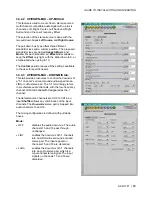
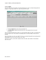
3.3.2 Dynamic
Processing
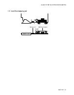
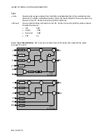
This process is part of the input processor, refer to
the block diagram.
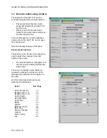
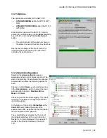
3.3.2.1 CH 1 to CH 4 tabs:
Each of these tabs controls the dynamic
processing for one channel. The available
functions are Limiter, Compressor, and Downward
Expander. A Gain trim allows compensation of the
loudness attenuation that follows compression.
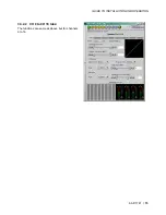
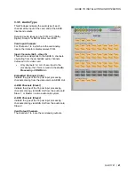
A graphic of the input to output transfer function,
VU
and
PEAK
meters for the program, and
compression meter will facilitate the adjustments
for each channel. Eight channel metering is active
for one minute only after any setting modification
on the current tab, or after a click on
Dynamics
for 1 min
box.
At any time a
Bypass
Settings
checkbox allows
immediate comparison between processing ON or
OFF.
The
Mode
pull-down menu is used to link two or
more channels, so they can share the same
dynamic controls to keep a coherent stereo or
multi channel image. The stereo choice links an
odd channel with (odd + 1) channel.
The
Dynamic Gain
is adjusted from 0 to +24 dB gain with the slider or a direct keyboard entry.
The
Limiter Threshold
is adjusted from 0 to -20 dBFS with the slider or a direct keyboard entry. 0 is the
default value and corresponds to
Limiter
OFF. For analog inputs, the correspondence between the dBFS
and the dBu values depends on the Input 0 dBFS setting (
Audio Processing
Tab -
Config
sub-tab).
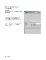
The proposed parameters for the
Compressor
are the
Attack Time, Release Time
,
Threshold
and
Ratio
.
The Threshold is adjustable with a slider between -60 and 0 dBFS, 0 is the default value and corresponds
to an
OFF position. The other parameter values are accessible via pull-down boxes.
The proposed parameters for the downward
Expander
are
Threshold
and
Ratio
. The output on input ratio
of 1/1 is the default value and corresponds to the
OFF position. The
Threshold
is accessible via a pull-
down box.
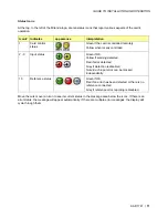
At the bottom of the tab, from left to right, appear the dynamic meters and the
VU
and
PEAK
meters.
The dynamic meter moves downward and gives the attenuation applied to the audio channel, the
Dynamic
Gain
effect is not displayed. The top of the scale is for 0 dB. The scale goes from 0dB at the top to -31 dB
at the bottom.
•
The VU meter is displayed with a bar and the PEAK meter with a dot.


