35
6.3.
To improve access to the terminals on top of the tank the terminal block may be
loosened by removing the fixing screw.
6.4.
Remove the screws that hold the clamp bracket in position and remove the clamp
bracket.
6.5.
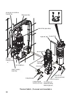
Remove the screws that hold the flow valve and switch assembly and the heater
tank in position.
6.6.
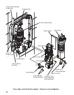
Carefully pull the flow valve and switch assembly and the heater tank away from
the case.
6.7.
Remove the brown and red wires from one side of the thermal switch and the
second brown wire from the other side of the thermal switch.
6.8.
Remove the fixing screw and remove the thermal switch and green earth bonding
wire.
Caution!
Do not press printed disc on the replacement thermal switch as this
will make the component unserviceable.
6.9.
Refit the components in reverse order. Make sure that the electrical wires are
installed in the correct positions. In particular the green earth bonding wire must
be reconnected above the thermal switch flange.
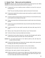
6. Thermal Switch - Removal and Installation
WARNING!
Isolate the electrical and water supplies before removing the cover. Mains
electricity connections are exposed when the cover is removed.
6.1.
Unscrew the four cover retaining screws sufficient to remove the cover and
service tunnel.
Note!
The cover retaining screws are captive and need not be removed.
6.2.
Remove the hose from the outlet connector and loosen the connection to the inlet
connector assembly.
Содержание elite 2
Страница 8: ...8 Power Low Flow Low High Temperature Start Stop Medium Dimensions Section 4 270 mm 85 mm 344 mm ...
Страница 41: ...41 Notes ...
Страница 42: ...42 Notes ...
Страница 43: ...43 Notes ...

