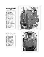
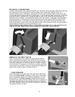
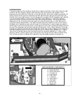
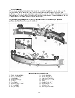
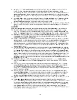

OFF-AISLE WAND TOOL
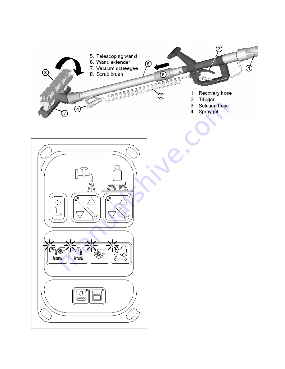
The off-aisle wand tool as described in the previous page is composed of the following items:
1. The
recovery hose
is connected to the end of
the wand on one end and to the diverter
assembly (item
F
) on the other end. This hose
has swivel cuffs on both ends that allow the
operator a good range of motion and the
solution hose to be inside the recovery hose.
2. The
trigger
controls the solution flow to the
spray jet. Squeezing the trigger opens an
internal valve to dispense cleaning solution.
3. The
coiled
solution hose
acts as a conduit
from the trigger to the spray jet, and allows
hose to be extended along with the wand.
4. The
spray jet
dispenses the cleaning solution
to soak soiled areas that are not accessible to
the main scrub deck.
5. The
telescoping wand
allows the length to be
adjusted for operator comfort and better
storage when not in use.
6. Sliding
the
wand extender
forward (as shown
above) extends the wand length during use
and retracts the wand by pulling it back for the
storage position.
7. The flip-flop tool gives the operator complete
flexibility when changing from the
scrub
brush
mode to
vacuum squeegee
mode by
simply rotating the end.
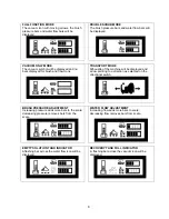
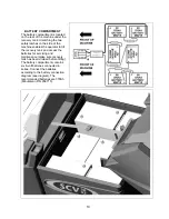
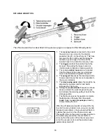
When the off-aisle wand switch is turned ON, the
four (full function, double scrub, vacuum only and
transport) mode lights in the keyboard will flash to
indicate that you are in the off-aisle tool mode.
This switch turns on the pump to supply solution to
the wand spray jet and the vacuum motor to
recovery the dirty water. When the recovery tank
is full, the vacuum motor and the solution pump
automatically shuts off.
16
Содержание SCV28
Страница 1: ...SCV 28 32 RIDER SCRUBBER OPERATION SERVICE PARTS CARE ...
Страница 3: ...3 ...
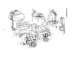
Страница 31: ...EXPLODED VIEWS MAIN ASSEMBLY I 25 ...
Страница 32: ...26 ...
Страница 33: ...MAIN ASSEMBLY II 27 ...
Страница 34: ...28 ...
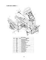
Страница 35: ...MAINFRAME ASSEMBLY I 29 ...
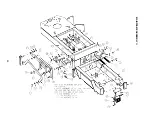
Страница 36: ...MAINFRAME ASSEMBLY II 30 ...
Страница 37: ...31 ...
Страница 38: ...FRONT DRIVE ASSEMBLY 32 ...
Страница 39: ...33 ...
Страница 40: ...STEERING ASSEMBLY 34 ...
Страница 41: ...35 ...
Страница 42: ...LCD HOUSING ASSEMBLY 36 ...
Страница 43: ...SOLUTION TANK ASSEMBLY 37 ...
Страница 44: ...38 ...
Страница 45: ...ELECTRICAL PANEL ASSEMBLY 39 ...
Страница 46: ...CONSOLE ASSEMBLY 40 ...
Страница 47: ...RECOVERY TANK ASSEMBLY I 41 ...
Страница 48: ...42 ...
Страница 49: ...RECOVERY TANK II 43 ...
Страница 50: ...DIVERTER ASSEMBLY 44 ...
Страница 51: ...BATTERY BOX ASSEMBLY 45 ...
Страница 52: ...PUMP ASSEMBLY 46 ...
Страница 53: ...47 ...
Страница 54: ...REAR AXLE ASSEMBLY 48 ...
Страница 55: ...SQUEEGEE MECHANISM ASSEMBLY 49 ...
Страница 56: ...REAR SQUEEGEE ASSEMBLY 28 50 ...
Страница 57: ...51 ...
Страница 58: ...REAR SQUEEGEE ASSEMBLY 32 52 ...
Страница 59: ...53 ...
Страница 60: ...28 CYLINDRICAL SCRUB DECK ASSEMBLY 54 ...
Страница 61: ...55 ...
Страница 62: ...28 DISC SCRUB DECK ASSEMBLY 56 ...
Страница 63: ...57 ...
Страница 64: ...32 CYLINDRICAL SCRUB DECK ASSEMBLY 58 ...
Страница 65: ...59 ...
Страница 66: ...32 DISC SCRUB DECK ASSEMBLY 60 ...
Страница 67: ...61 ...
Страница 68: ...CYLINDRICAL DECK AND SIDE SQUEEGEE MOUNTING 62 ...
Страница 69: ...63 ...
Страница 70: ...DISC SCRUBDECK AND SIDE SQUEEGEE MOUNTING 64 ...
Страница 71: ...65 ...
Страница 72: ...28 SIDE SQUEEGEE RIGHT SIDE 66 ...
Страница 73: ...28 SIDE SQUEEGEE LEFT SIDE 67 ...
Страница 74: ...32 SIDE SQUEEGEE RIGHT SIDE 68 ...
Страница 75: ...32 SIDE SQUEEGEE LEFT SIDE 69 ...
Страница 76: ...OFF AISLE WAND ASSEMBLY 70 ...
Страница 77: ...71 ...
Страница 78: ...PLUMBING DIAGRAM 72 ...
Страница 79: ...WIRING DIAGRAMS POWER WIRING 73 ...
Страница 80: ...INPUTS TO CONTROLLER 74 ...
Страница 81: ...OUTPUTS FROM CONTROLLER 75 ...
Страница 82: ...KEYBOARD WIRING 76 ...
Страница 83: ...MACHINE SCHEMATIC 77 ...
Страница 84: ...1 03 78 ...


