background image

3

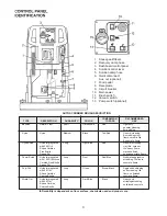
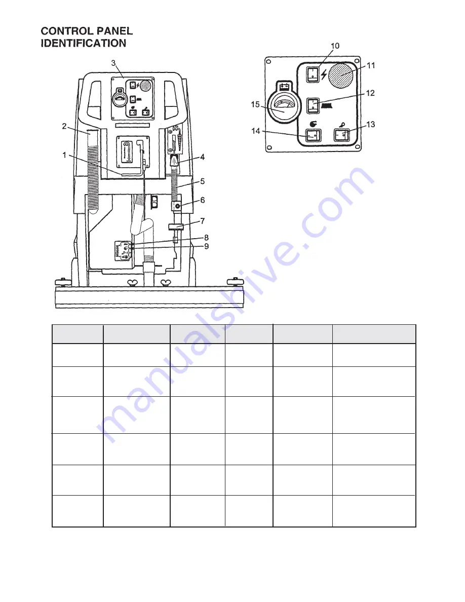
1. Squeegee lift lever
2. Recovery dump hose
3. Dashboard control panel
4. Solution control lever
5. Solution dump hose
6. Quick disconnect

Aux. out (optional)

7. Food pedal
8. Receptacle
9. Circuit breaker

10. Main power

11. Brush switch

12. Vacuum switch
13. Pump switch (optional)

COMPARISON

RECOMMENDED

TYPE

DESCRIPTION

DURABILITY*

COLOR

TO PADS

USE

Bassine

Natural Fiber

Short

Dark Brown

Red

Light duty
general cleaning,
acid etching

Nylon

Nylon

Medium

Black

Tan/Red

General cleaning
& scrubbing vinyl

floors, ceramic tile
& concrete floors

Dyna-Scrub

Nylon impregnated

Long

Light Blue

Red

General scrubbing,

with 500 Grit

vinyl tile, ceramic

Silicon Carbide

tile, epoxy floors,

Fine Bristle,

urethane finish,

Dense Fill

uneven concrete floors

Power-Scrub

Nylon impregnated

Long

Rust

Red/Blue

Moderate aggressive

with 120 Grit Silicon

scrubbing, tile floors,

Carbide Fine Bristle,

concrete floors

Dense Fill

Poly-Grit

Nylon impregnated

Long

Green

Brown/Black

Aggressive stripping

with 80 Grit

and scrubbing, tile

Silicon Carbide

floors, unfinished

Coarse Bristle

concrete floors

Strata-Grit

Nylon impregnated

Long

Dark Blue

Black

Heavy duty

with 46 Grit

stripping/scrubbing

Silicon Carbide

unfinished concrete

Coarse Bristle

AUTO SCRUBBER BRUSH DESCRIPTION

•••••


Durability is dependent on floor surface, chemicals used and proper care.

Содержание MC20003QP

Страница 1: ...200X Brush Drive Floor Scrubber Electric Model MC20003QP MC20004CE Revised 6 02 OPERATION SERVICE PARTS CARE ...

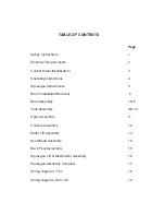
Страница 2: ...uctions 4 Squeegee Adjustments 5 Brush Installation Removal 6 Base Assembly 7 8 Tank Assembly 9 10 Upper Assembly 11 Console Assembly 12 Motor Lift Assembly 13 Scrubhead Assembly 14 Back Panel Assembly 15 Squeegee Lift Mechanism Assembly 16 Squeegee Assembly Complete 17 Wiring Diagram 115V 18 Wiring Diagram 230V CE 19 ...

Страница 3: ......

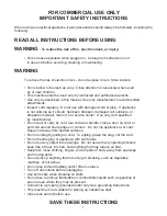
Страница 4: ...ter Use only cord specified by manufacturer Do not pull or carry by cord use cord as a handle close a door on cord or pull cord around sharp edges or corners Do not run appliance over cord Keep cord away from heated surfaces Do not unplug by pulling on cord To unplug grasp the plug not the cord Do not handle plug or appliance with wet hands Do not put any object into openings Do not use with any o...

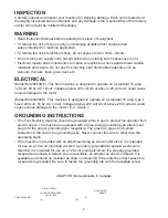
Страница 5: ... This machine is designed to operate on a standard 16 amp type L fused 230 volt 50 hz AC circuit Voltages below 200 volt AC or above 250 volts AC could cause serious damage to the motor I E C Class 1 GROUNDING INSTRUCTIONS This floor finishing machine should be grounded while in use to protect the operator from electric shock The machine is equipped with a three prong grounding type attachment plu...

Страница 6: ...ed Long Light Blue Red General scrubbing with 500 Grit vinyl tile ceramic Silicon Carbide tile epoxy floors Fine Bristle urethane finish Dense Fill uneven concrete floors Power Scrub Nylon impregnated Long Rust Red Blue Moderate aggressive with 120 Grit Silicon scrubbing tile floors Carbide Fine Bristle concrete floors Dense Fill Poly Grit Nylon impregnated Long Green Brown Black Aggressive stripp...

Страница 7: ...brush first push the pedal 7 slightly outward on the machine unlock it and then release it slowly To lift the brush press the pedal 7 down until lift mechanism engages 5 Turn on brush 11 6 Adjust solution control feed lever 4 7 Turn on vacuum switch 12 8 Lower squeegee assembly by lowering handle 1 After Use 1 Turn off solution feed 4 2 Switch off brush 11 and raise 7 3 Raise squeegee assembly 1 4...

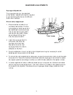
Страница 8: ...ard to check the rear squeegee blade for uniform deflection to the floor 3 If uneven deflection or lay is evident minor adjustments may be necessary to avoid streaking and uneven wear on the blade 4 To correct this pitch adjustment is necessary Loosen the pivot screw item 2 and the pitch screw item 3 Move the machine forward and allow the squeegee to level itself or adjust the angular position acc...

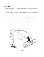
Страница 9: ...r the scrubhead shroud while lining up the center hex drive hub and pressing the brush up until the brush engages on the drive hub REMOVAL 1 Raise the scrubhead to the UP position by depressing the pedal A downward as shown on Fig 1 2 Remove the brush D by stepping on the BRUSH RELEASE PIN on the top of the scrubhead shroud as shown on Fig 1 below Figure 1 ...

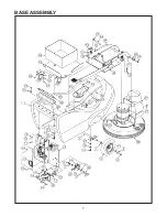
Страница 10: ...7 BASE ASSEMBLY ...

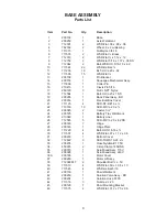
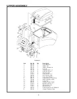
Страница 11: ... Electrical Box Cover 21 711125 4 SCR ST B 10 x 22 710180 10 SCR MC 20 x 23 200345 2 Caster 3 24 200125 1 Battery Tray Weldment 25 210048 1 Battery Liner 26 712565 5 SCR MC 20 x 62 SS 27 200145 1 Hinge 28 200146 1 Hinge Plate 29 711228 4 Bolt HH 5 16 18 x 30 711507 4 WSR Flat 37 x 1 12 x 06 31 200233 1 Bottom Cover 32 712822 3 SCR THMS 10 24 x 33 200235 1 Hose Nylobraid 17 50 34 450076 2 Crimp Cla...

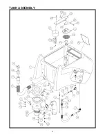
Страница 12: ...9 TANK ASSEMBLY ...

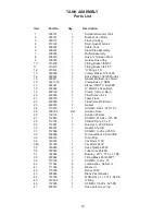
Страница 13: ...Filter Screen 4 x 4 21 260155 1 Foam Float 22 430090 1 Float Valve Weldment 23 460019 2 Gasket 24 710207 1 SCR MC 6 32 x 87 ST PL 25 200234 Ref Solution Hose 26 130118 1 Solution Strainer 27 712540 3 SCR MC 10 24 x 375 SS 28 712574 1 CR Bolt SS 20 x 3 29 712667 2 Nut Hex 20 SS Nyloc 30 200231 1 Gasket Shutoff 31 712568 1 SCR MC 20 x 2 25 SS 32 832996 1 Terminal Block 2 Pole VDE 33 833316 1 Drain P...

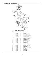
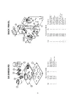
Страница 14: ...MC 20 x 7 711503 2 WSR Flat 10 8 711125 5 SCR ST B 10 x 9 760286 1 Wire Formed Hook 10 200176 1 Dump Hose Bracket 11 200170 1 Console Assy Brush Drive 12 715284 1 Decal Solution Control 13 383367 1 Spring Clip 14 430053 1 Solution Control Cable 15 711228 6 Bolt HH 5 16 18 x 16 711545 6 WSR Helical 5 16 17 711575 6 WSR Flat 5 16 18 200032 1 Console Back Cover Weldment 19 450054 1 Vacuum Recovery Ho...

Страница 15: ...5 6 WSR Flat 31 x 75 x 06 9 711545 6 WSR Helical 5 16 10 711228 6 Bolt HH 5 16 18 x 75 11 711505 2 WSR Flat 12 200240 1 Squeegee Lift Assy 13 711544 6 WSR Helical 14 711203 6 Bolt HH 20 x 62 15 740812 3 Switch optional 4th 16 740811 3 Switch Boot optional 4th 17 833827 1 O Ring 1 25 ID x 187 18 250038 1 Retainer Bag Clip 19 830292 1 Cord Assy 75 ft 115V 19A 743287 1 Cord Assy 25 Meters 240V 20 430...

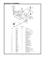
Страница 16: ...ch 11 711430 1 Tinnerman Clip 12 833638 2 Brass Stud 13 711368 2 Wing Nut 14 740132 2 Insulator Glastic 15 711546 2 WSR Helical 3 8 16 711241 2 Bolt HH 3 8 16 x 17 711376 1 Nut Nyloc 13 18 260137 1 Compression Spring 19 200110 1 Spring Bracket 20 200149 1 Adjustment Rod 21 200116 1 Pedal Arm Weldment 22 762294MCH 1 Pedal 23 711202 2 Bolt HH 20 x 24 711544 2 WSR Helical 25 450040 2 Elbow 3 8 Barb x...

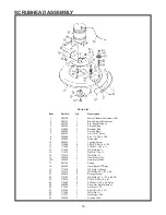
Страница 17: ...8 16 x 1 00 12 711202 3 SCR MC 20 x 13 711544 3 WSR Helical 14 711615 1 Roll Pin 1 8 x 15 712318 1 WSR Flat 16 740428 1 Gear Motor 115V 16A 740432 1 Gear Motor 240V 17 833102 1 Spring 18 833325 1 Hose Barb 90 Nylon 19 711578 2 WSR Flat Brass 20 712310 8 WSR Flat 52 x 87 x 06 21 430085 2 Bumper Wheel 22 712759 2 WSR Flat 31 x 1 37 x 06 SS 23 710975 2 SCR SC 5 16 18 x 87 24 712560 8 SCR MC 20 x 50 N...

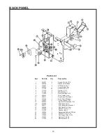
Страница 18: ... 200332 1 Wire Guard Cover 10 200311 1 Back Panel Weldment 11 742748 1 Boot Circuit Breaker 12 740220 1 Circuit Breaker 20A 13 830540 1 Flg Male Receptacle 115V 13A 832682 1 230V Receptacle 14 200317 1 230V Receptacle Bracket 15 742256 1 RFI Filter 230V Only 16 712818 2 SCR MC 10 24 x 5 17 741300 1 Terminal Block 18 740202 1 Receptacle Bridge 230 Only 19 712813 5 SCR MC 10 24 x 75 20 712908 2 Nut ...

Страница 19: ...s List for 200265 Item Part No Qty Description 1 200124 1 Backpanel Weldment 2 742749 2 Circuit Breaker Plug 3 711368 2 Wing Nut 20 4 740132 2 Insulator Glastic 5 742748 2 Boot Circuit Breaker 6 740247 1 Circuit Breaker 30 7 742000 2 Diode Assembly 8 740549 1 Circuit Breaker 50 9 711210 2 SCR HH 20 x 1 10 740159 1 CB175 Red Housing Only 11 743260 1 Wire Harness 200X BD 12 788147 2 Solenoid 24VDC 1...

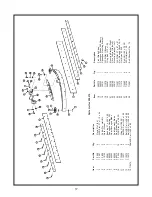
Страница 20: ...72 2 Bolt SS Carr 20 x 2 00 14 712573 2 Bolt SS Carr 20 x 2 50 15712574 2Bolt SS Carr 20 x 3 00 Item Part No Qty Description 16 260273 1 Front Blade Strap 17 260322 1 Squeegee Blade 260 Quarry 18 320191 1 Squeegee Mounting Bracket 19 711578 2 WSR Flat Brass 20 260287 2 Wing Bolt 13 x 1 00 21 320156 1 Mounting Bracket Right 22 200169 1 Pitch Control Weldment 23 320157 1 Mounting Bracket Left 24 712...

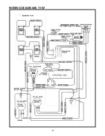
Страница 21: ...18 WIRING DIAGRAM 115V ...

Страница 22: ...19 WIRING DIAGRAM 240V CE ...

Страница 23: ... All warranteed items become the sole property of Minuteman International Inc or its original manufacturer whichever the case may be Minuteman International Inc disclaims any implied warranty including the warranty of merchantability and the warranty of fitness for a particular purpose Minuteman International Inc assumes no responsibility for any special incidental or consequential damages This li...

Отзывы: