


10. Testing the Throttle Potentiometer
1.
Check for a open or faulty potentiometer circuit
2.
The throttle potentiometer resistance can be measured with an ohmmeter.
3.
Analog type meters are recommended for this test, not digital.
4.
Locate the Trio controller. Unplug the P3 connector (the large white connector with 14 pins) on the controller under
the seat on the riders in the metal compartment.
5.
Locate black/white and the black/orange wires. The resistance measured across them should be 5K. If not, check
the connection near the throttle control potentiometer.
6.
If step 5 checks OK, locate the black/orange and the black/pink wire on the P3 connector. On ES2832 or CP2832
behinds the potentiometer must be in the full counter clock wise position and the drive switch activated. The seat
switch will need to be activated during this test on riders. Measure the resistance across the two. It should be zero
ohms in the neutral position. It should be about 5k in the full throttle position. The potentiometer will need to be
adjusted slowly while making the test.
Note: when moving the throttle to the full position, the resistance
should be smooth, without dropping out for both tests. If the resistance does not go to 5K ( 20%) during
the test, the arm and the potentiometer may need to be adjusted to achieve it on the riders.
8.
If your reading is different with this test, check all the connections between the controller and the throttle control
potentiometer, including the seat switch (Riders only). Retest at the connector near the throttle control
potentiometer.
9.
Unplug the throttle control potentiometer at the connector next to it.
10. Measure the resistance across the red and white wire on the potentiometer assembly. It should measure
approximately 5K (5 thousand ohms
20%).
1.
Check for a open or faulty potentiometer circuit
2.
The throttle potentiometer resistance can be measured with an ohmmeter.
3.
Analog type meters are recommended for this test, not digital.
4.
Locate the Trio controller. Unplug the P3 connector (the large white connector with 14 pins) on the controller under
the seat on the riders in the metal compartment.
5.
Locate black/white and the black/orange wires. The resistance measured across them should be 5K. If not, check
the connection near the throttle control potentiometer.
6.
If step 5 checks OK, locate the black/orange and the black/pink wire on the P3 connector. On ES2832 or CP2832
behinds the potentiometer must be in the full counter clock wise position and the drive switch activated. The seat
switch will need to be activated during this test on riders. Measure the resistance across the two. It should be zero
ohms in the neutral position. It should be about 5k in the full throttle position. The potentiometer will need to be
adjusted slowly while making the test.
Note: when moving the throttle to the full position, the resistance
should be smooth, without dropping out for both tests. If the resistance does not go to 5K (± 20%) during
the test, the arm and the potentiometer may need to be adjusted to achieve it on the riders.
8.
If your reading is different with this test, check all the connections between the controller and the throttle control
potentiometer, including the seat switch (Riders only). Retest at the connector near the throttle control
potentiometer.
9.
Unplug the throttle control potentiometer at the connector next to it.
10. Measure the resistance across the red and white wire on the potentiometer assembly. It should measure
approximately 5K (5 thousand ohms ± 20%).
Page 43
Содержание ES2832
Страница 6: ...2 1 Minuteman System Maintenance K Page 6 ...
Страница 7: ...2 2 Minuteman System Maintenance I Page 7 ...
Страница 8: ...2 3 Minuteman System Maintenance II Page 8 ...
Страница 9: ...2 4 Minuteman System Maintenance S Page 9 ...
Страница 17: ...4 2 ES2832 CP2832 and Phoenix 34 Locate the Red Black wire group Locate the Orange Violet wire Page 17 ...
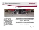
Страница 34: ...7 5 Rear Squeegee Adjustment SCV2426 SCV2832E Only Page 34 ...
Страница 35: ...7 6 Rear Squeegee Adjustment SCV2426 SCV2832E Only Page 35 ...
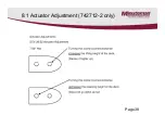
Страница 38: ...8 1 Actuator Adjustment 742712 2 only Page 38 ...
Страница 49: ...13 Notes ...


