background image


miniDSP Ltd – Hong Kong / Email : 

[email protected]

 / Features and Specifications are subject to change without prior notice 

P 12 


4.3.1


Custom Label 

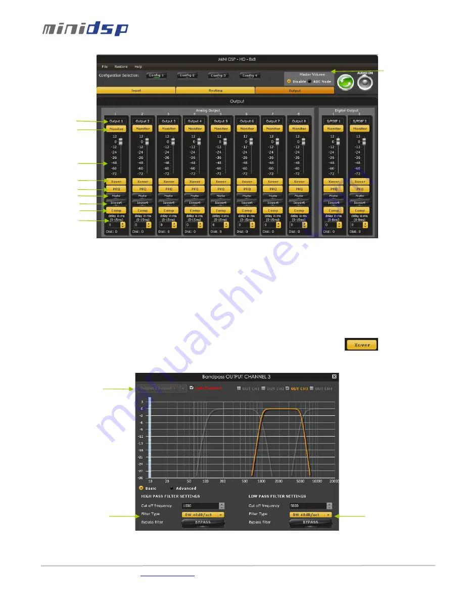
The custom label feature allows you to input a user defined label for each output channels: A handy feature to remember the output 
configuration of your system.  

4.3.2


Monitor 

Allows you to monitor the input meter of that specific channel on a RMS meter. Note that the information is shown in dBFS 

4.3.3


Output volume 

A fader control for +12 to -70dB digital gain control. Similar to the input volume control.  

4.3.4


Crossover  

Controls for the Low& High pass filters are available when clicking on the Xover (crossover) button: 
The log scale graph gives you the equivalent response of the applied filter. By pointing the mouse anywhere on the plotted curve, the 
dB attenuation and respective frequency are displayed. 


Cut off frequency: Select the -3dB frequency by either entering the value or using the up & down arrows of the numeric 
box. 


Filter types:  

Custom label 

Monitor 

Output volume 

Crossover control 

PEQ control 

Mute control 

Polarity control 

Output delay 

Linking Features 

Low Pass Filter 

settings 

High Pass Filter 

settings 

Master volume 
control 

Compressor/limiter 

Содержание 10X10 HD

Страница 1: ...inidsp com Features and Specifications are subject to change without prior notice P 1 miniDSP 10x10 Hd USER MANUAL Revision Description Date V1 0 Initial revision 28 06 2012 V1 1 Volume control config...

Страница 2: ...tecture 9 4 1 1 Main Page 9 4 1 2 Preset Memory selection 10 4 1 3 Input Tab 10 4 2 Matrix Tab 10 4 3 Output Tab 11 4 3 1 Custom Label 12 4 3 2 Monitor 12 4 3 3 Output volume 12 4 3 4 Crossover 12 4 3...

Страница 3: ...matically saved to both the DSP and the Flash for long term memory Once happy with your configuration you can disconnect the board from your computer since from this point on the audio configuration w...

Страница 4: ...nd won t cause any damage to your system Once again miniDSP can not be responsible of any damages the board make cause to your system Finally MiniDSP is a very flexible board and 99 of typical questio...

Страница 5: ...em Connectivity 2 1 Board connectivity Front View Rear View 2 2 Typical setup The following diagram is a typical connectivity diagram for a basic setup with analog inputs analog outputs To prevent any...

Страница 6: ...tor 2Vrms 8 dBu or 0 9Vrms depending on input jumper position Phoenix Terminal block 4Vrms 14 dBu with an unbalanced signal 8Vrms with a balanced signal 20dBu Maximum Output signal 0dBFS RCA connector...

Страница 7: ...ws user to control the output gain both the unbalanced and balanced outputs on a per channel basis 2 3 Front panel control The miniDSP 10x10 has a rotary front panel for control of 3 elements of the p...

Страница 8: ...the plug in will automatically boot up 4 You can now connect the miniDSP board to one of the USB 2 0 port of your PC The device will be recognized as a HID driver and does not require any driver insta...

Страница 9: ...you have b Restore to Default With this option the software application resets all settings back to factory default and reload the firmware Warning that all current settings will be lost and there are...

Страница 10: ...configuration We therefore recommend that you perform a quick configuration offline without being connected synchronized to the processor to prevent any damage to your equipment 4 1 3 Input Tab The fi...

Страница 11: ...utput 2 only Etc Note how labels of input channels and output channels followed on the Matrix mixer to simplify your routing Let s illustrate the concept of configuration of this block using a 3way co...

Страница 12: ...in control Similar to the input volume control 4 3 4 Crossover Controls for the Low High pass filters are available when clicking on the Xover crossover button The log scale graph gives you the equiva...

Страница 13: ...g feature will link these two channels together Step 2 Click on the Link tick box to enable the linking Note that the environment will warn you that all current PEQ settings of the current channel wil...

Страница 14: ...configuration from the software to be enabled Please make sure to select the IR mode to make sure your unit is correctly configured 4 4 Load Save Restore a configuration 4 4 1 Load configuration Use t...

Страница 15: ...synchronization if you have the incorrect firmware loaded on your platform Once the new plug in installed please browse to Program Files MiniDSP MiniDSP 8x8 firmware_tools Windows Three files can be...

Страница 16: ...figured these first To program a command 2 simple steps While connected and synchronized Press the LEARN button Point the remote to the IR receiver and press the button to learn the command A dialog b...

Страница 17: ...matrix mixer is set to send audio to the output channels in a mixer plug in Check the output mute status for each channel 10 4 Cannot reload configuration Confirm the file format of your file xml Conf...

Отзывы: