User Manual of DH-300/400 Full Automatic Soldering Robot
11
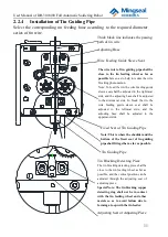
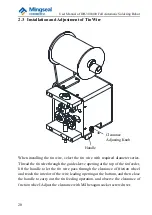
2.2.4
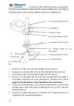
Installation of Tin Guiding Pipe
Select the corresponding tin feeding hose according to the required diameter
series of tin wire.
Adjusting Seat of Adjusting Piece
The wire inlet of tin guiding pipe shall be
close to the tin feeding wheel as far as
possible
here so as to help to reduce the wire
blocking phenomenon.
Note: To feed the tin, the wire feeding guide
sleeve seat shall be adjusted to the rightmost
side, and the adjusting base shall be adjusted
to the downmost side. To break the tin, the
wire feeding guide sleeve seat shall be
adjusted to the leftmost side, and the
adjusting base shall be adjusted to the
uppermost side.
Tin Blocking Detecting Piece
The tin blocking detecting piece shall be
close to the tin feeding wheel as far as
possible, and the vertical position can be
adjusted through the adjusting seat of
adjusting piece.
Special Note: The tin blocking copper
detecting ring shall not be in contact
with the tin feeding wheel and other
metals so as to avoid failure due to
forming a loop with the tin feeder.
Fixed Seat of Tin Guiding Pipe
Tin Guiding Pipe
Note: This is where the shoulder and the
bottom of the fixed seat of tin guiding
pipe shall fit together as far as possible.
Thick black line indicates the passing
path of tin wire
Adjusting Base
Wire Feeding Guide Sleeve Seat


