


P A G E 8
E a s y P I C P R O v 8 M a n u a l
1
2
3
4
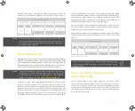
P O W E R S U P P L Y
P A G E 8
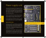
Figure 1: P
ow
er supply unit view
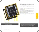
Power supply unit
The power supply unit (PSU)
(1)
provides clean and regulated power, necessary
for proper operation of the development board. The host MCU, along with the
rest of the peripherals, demands regulated and noise-free power supply.
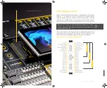
Therefore, the PSU is carefully designed to regulate, fi lter, and distribute the
power to all parts of the development board. It is equipped with three diff erent
power supply inputs, off ering all the fl exibility that EasyPIC PRO v8 needs,
especially when used on the fi eld. In the case when multiple power sources are
used, an automatic power switching circuit with predefi ned priorities ensures
that the most appropriate will be used.
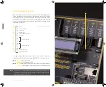
The PSU also contains a reliable and safe battery charging circuit, which allows
a single-cell Li-Po/Li-Ion battery to be charged. Power OR-ing option is also
supported, providing uninterrupted power supply (UPS) functionality when an
external or USB power source is used in combination with the battery.
The digitally controlled programmable voltage output can be used as a voltage
reference for various purposes, including A/D or D/A converters, comparators,
and other peripherals that require or can use an external reference voltage.
The programmable voltage output can be controlled over the CODEGRIP Suite.
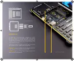
Detailed description
The PSU has a very demanding task of providing power for the host MCU and
all the peripherals onboard, as well as for the externally connected peripherals.
One of the key requirements is to provide enough current, avoiding the voltage
drop at the output. Also, the PSU must be able to support multiple power sources
with diff erent nominal voltages, allowing switching between them by priority. The
PSU design, based on a set of high-performance integrated devices produced by
Microchip, ensures a very good quality of the output voltage, high current rating,
and reduced electromagnetic radiation.
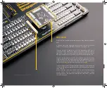
At the input stage of the PSU, the MIC2253, a high-effi ciency boost regulator
IC with overvoltage protection ensures that the voltage input at the next stage
is wellregulated and stable. It is used to boost the voltage of low-voltage power
sources (a Li-Po/Li-Ion battery and USB), allowing the next stage to deliver well-
regulated 3.3V and 5V to the development board. A set of discrete components
are used to determine if the input power source requires a voltage boost.
(1)
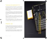
This image is only for demonstration purpose, please do not
remove the PSU plastic cover nor touch any of the components below.
The development board can be permanently damaged.
Содержание EasyPIC PRO v8
Страница 5: ...E a s y P I C P R O v 8 M a n u a l P A G E 5...
Страница 26: ...The 8th generation of hardware perfection...
Страница 27: ......
Страница 29: ......


