background image

6x

M3x10

1x

M3x3

M2,5x10

4x

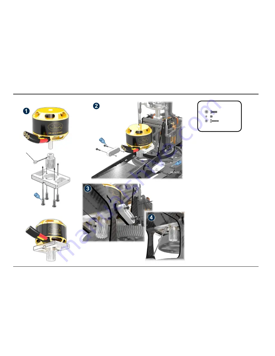
Installation of Motor and Gear Mesh

1) Mount the motor as shown in image (1), using the four 

countersunk screws M3x10. Make sure that the M3x3 set 

screw is placed at the flattened area of the motor shaft. Do 

not fasten the set screw now (it can only be used once!) 

-  the pinion will be positioned later.

2) Mount the motor plate, as shown in (2), using the four 

set screws M2.5x10 and the additional aluminum braces. 

Do not tighten the screws completely, as the entire motor 

plate should be still moveable.

3) Push the motor with pinion as close to the main gear as 

possible, see image (3). The centers of the herringbone of 

pinion and main gear must be aligned exactly. The main 

gear has a slight axial play for easy adjustment.

4) Now fix the pinion to its final position by tightening the 

M3x3 set screw. This set screw can only be used once.  

You must secure it by using thread lock!

5) Pinion and main gear should have minimal gear mesh. 

The main gear is not 100 % round (due to the free wheel 

unit).  Therefore there will be a small area without any 

gear mesh. This is normal. Do not use paper for setting 

the gear mesh (this does not work with the herringbone 

gear!). Now secure the M2.5 socket head cap screw with 

thread lock.

6) During pre-flight check, before each flight, the gear 

backlash must be checked! Also, the gear must be che-

cked for wear and tear. If necessary, adjust the gear mesh 

and/or replace the gears. Note that the motor ball bearing 

can also be subject to wear and tear, as well as to excess 

play.

Bag 6

Do not tighten yet!

Manual LOGO 480 - ©Mikado Model Helicopters GmbH -2013- Page 12  

10 Motor Installation

Bag 6

M2,5x10

M3x10

M2,5x10

Содержание Logo 480

Страница 1: ...Manual Mikado Model Helicopters GmbH Friedrich Klausing Stra e 2 14469 Potsdam Germany phone 49 0 331 23749 0 fax 49 0 331 23749 11 www mikado heli de Mikado Model Helicopters GmbH 2013 V1 0019...

Страница 2: ...n Gear 9 8 Swashplate 10 9 Rotor Head 11 10 Motor Installation 12 11 Wiring RC Components 13 12 Wiring RC Components Battery Mounting 14 13 Canopy and Overview 15 14 Overview Spare Parts Mainframe 16...

Страница 3: ...servo screws with thread lock Loctite Please secure the servo screws with thread lock Loctite Please secure the servo screws with thread lock Loctite Manual LOGO 480 Mikado Model Helicopters GmbH 2013...

Страница 4: ...x7 18x 2x 4x M2 5 M3 3x7x3 2x 3x17 4x 3x5x2 5 4x M3x8 Bag 1 Secure all srews with thread lock Manual LOGO 480 Mikado Model Helicopters GmbH 2013 Page 4 2 Mainframe Bag 1 M3x16 M2 5x8 M2 5x6 M2 5x6 M3x...

Страница 5: ...M3 M3x3 4x 4x 10x19x5 SW5x19 4x M3x20 Bag 5 Bag 1 Secure all srews with thread lock Manual LOGO 480 Mikado Model Helicopters GmbH 2013 Page 5 3 Landing Struts Bag 1 5 M3x16 M3 Stopp M3x3 M3x16 M3x20...

Страница 6: ...1x 3x5x0 5 1x M3x14 2x 3x6x2 5 Bag 7 Bag 7 Bag 5 Large inner diameter Small inner diameter Apply grease on bearing Do not apply thread lock here Apply thread lock only in the theaded section inside t...

Страница 7: ...x450 mm Kugel 6 mm M2x6 M2 Stopp M3x30 4x480 mm 2x M3x30 2x M3 4x Kugel ball Rotule 6x3 4x 2x 2x M3x16 2x 1x M2x6 1x M2 Stopp Bag 8 Ball 6 mm Bag 7 Bag 8 11 Bag 8 11 Manual LOGO 480 Mikado Model Helic...

Страница 8: ...Manual LOGO 480 Mikado Model Helicopters GmbH 2013 Page 8 6 Tail Boom Brace M3x14 M3x14...

Страница 9: ...ease to the one way bearing After installing the belt pulley check the direction of the tail rotor Turn the main rotor clockwise The tail must also turn clockwise After mounting the main gear it will...

Страница 10: ...ll bolts with thead lock A hint for mounting the ball links One surface of the ball link is easier to clip on If link is too hard to clip on turn it by 180 degrees Manual LOGO 480 Mikado Model Helicop...

Страница 11: ...0 Large inner diameter 6 2mm Small inner diameter 6 0mm Apply grease to bearing Mounting direction is not critical Prior to assembly please supply silicon oil or grease on o rings and spindle shaft Ce...

Страница 12: ...asy adjustment 4 Now fix the pinion to its final position by tightening the M3x3 set screw This set screw can only be used once You must secure it by using thread lock 5 Pinion and main gear should ha...

Страница 13: ...2 Now attach the controller in its final position on the carbon plate using velcro and cable straps Make sure that the printed sticker faces upwards as it contains the heat sink 3 Connect the master...

Страница 14: ...94 and braided sleeving wrap item no 4593 Prior to each flight check all cables to make sure they are whole and not damaged Prior to each flight check that all connectors firmly connected We recommend...

Страница 15: ...e canopy Before each flight check that the canopy sits securely If the canopy sits too lose this can deteriorate the flight performance of the helicopter If the canopy becomes lose during flight the h...

Страница 16: ...9 19 teeth M0 5 4120 20 teeth M0 5 4121 21 teeth M0 5 4122 22 teeth M0 5 4123 23 teeth M0 5 4820 4278 4465 1344 10x 10x 3x 10x M2 5 4552 M3 4553 M2 5x27 4834 1565 04835 Canopy LOGO 480 neon yellow red...

Страница 17: ...4425 EDGE 86 2462 3049 2397 4828 4825 4826 Set 4827 4827 2444 3051 2447 4235 4831 1962 4274 3069 2466 4832 4232 2476 4830 3077 Manual LOGO 480 Mikado Model Helicopters GmbH 2013 Page 17 15 Overview S...

Страница 18: ...33 4205 1975 951 4834 27mm 1565 930 2330 Concieved and Constructed by Mehran Mahinpour Tirooni Rendering Andr Doil Layout Realisation Andr Doil www mikado heli de Manual LOGO 480 Mikado Model Helicopt...

Отзывы: