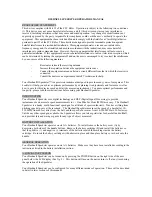
INTRODUCTION
Your 40 channel Mobile CB represents the state-of-the art in high-tech engineering. This compact
package, big in performance, is a quality piece of electronic equipment, skilfully constructed from
the finest components. The circuitry is all a solid-state, mounted on rugged printed circuit boards.
It is designed for many years of reliable, trouble-free performance. The night-light buttons allow
the night use.Your mobile CB has a built 40 Channel Phase-Locked Loop synthesizer circuit.
The PLL circuit achieves a new technique for generating all the required frequencies with fewer
crystals. The result is much tighter frequency control and superior reliability.
ALAN 48 EXCEL E40 presents an innovative device that makes this transceiver different from the
previous units: “ESP 2” is a dynamic cancelling filter that reduces noises disturbing audio signals.
It makes for enhanced audibility for a truer and a more understandable audio representation.
FUNCTION AND LOCATION OF THE CONTROLS
FRONT PANEL
1. Channel selector: it permits the manual channel selection.
2. Microphone jack : insert the mic connector in this jack.
3. Indicator: this meter indicates the receiving signal strength and the transmitter RF
output power.
4. Multifunction backlighted display . It shows:
a. channel selected number (from 1 up 40) or operative frequency
b. FUNC button activated
c. ESP: reducing noise device activated
d. DW: Dual Watch function activated
e. EMG: indicates channel being used or when the
emergency channels are activated
f. LOCK: keyboard lock function activated
g. SCAN function activated
h. M1-M2-M3-M4-M5: memory channel indicator
5. “FM” Indicator
6. “RX/TX” Indicator
LED indicating receiving or trasmitting mode. RX: green LED;
TX: red LED.
7. “CB/PA” Selector
In the “CB” position, the unit operates as a transceiver. You can use the PA (public address)
function only if you connect a speaker to the PA jack (“PA” visualized on the display). In this case
the “MIC” knob controls the amplification level.
INDEX
Introduction ................................................................................................................................ 1
Function and location of the controls ......................................................................................... 1
Installation .................................................................................................................................. 3
Power supply .............................................................................................................................. 3
Installing an antenna .................................................................................................................. 4
How to operate with your transceiver ......................................................................................... 4
Specifications ............................................................................................................................. 5
N.K.
M5
LOCK
M4
LCR
M3
SCAN
M2
DW
M1
EMG
FUNC
®
01
3
5 7 9 30
2
3 5 10
0
POWER
MIC
CH
VOL
SQ
MIC
RF
48 EXCEL
TX
RX AM
FM
GB/PA
1
2
3
4
5
6
7
8
9
10
11
12
13
14
16
18
15
17
F
ESP
DW
EMG
LOCK
SCAN
1
a
F
ESP
DW
EMG
LOCK
SCAN
b
c
d
e
f
g
h


