MCAC-TSM-2008-02
Description of Standard Unit
Installation
65
2. Description of Standard Unit
These air cooled reverse-cycle chillers with axial-flow fans operate with refrigerant fluid and are suitable for
outdoor installation.
They are factory tested and on site installation is limited to water and electrical connections.
Structure:
Panels and base are made from galvanized steel plate painted with epoxy powder to ensure total resistance
to atmospheric agents. Condensate collection pan as standard.
Compressors:
Scroll compressor with crankcase heater and thermal cut-out.
Evaporator:
AISI 316 stainless steel plate type evaporator complete with electric heater and differential pressure switch.
Casing lined with anti-condensate closed cell neoprene cladding.
Pump:
The units feature a pump with the moving parts in contact with the water made from corrosion resistant
materials, extra wear ring on the impeller, built-in capacitor for high starting torque and automatic venting of
impeller chamber.
Pump assembly:
Pump assembly with expansion tank, safety valve, auto water replenishing assembly, pressure gauge and
pump.
Condensing coil:
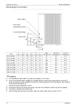
Made from copper tubes and high surface area aluminum fins. Condensing coil protection grills as standard.
Fans:
Axial-flow fans. Six-pole electric motor with built-in thermal cut-out. Housed in aerodynamic tubes with
accident prevention grill. Device for operation with low outside air temperatures: continuous fan rotation
speed control via condensing temperatures transducer.
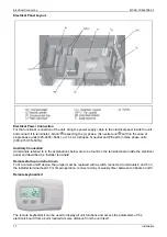
Power and control electrical panel
Power and control electrical panel constructed in accordance with IEC 204-1/EN60335-2-40, complete with
compressor contactor. Control via “HSW7” control panel.
Emergency stop push buttons
In case system crisis is occur (e. g: Compressor out of control ), press the emergency stop pushbuttons at
once, and turn it clockwise, until crisis is removed.
Optional accessories:
- Removable metal mesh filter.
- Remote keyboard kit.
- Additional pump.
The above accessories are optional. Consult the relative documentation for assembly instructions and
technical data.
Содержание MGC-F05W/N1
Страница 2: ......
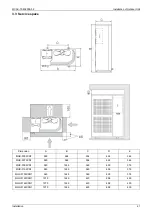
Страница 14: ...Specification MCAC TSM 2008 02 12 Installation 2 Dimensions unit mm 2 1 MGC F05W N1 MGC F07W N1...
Страница 15: ...MCAC TSM 2008 02 Outdoor units Outdoor units 13 2 2 MGC F09W N1 MGC F10W N1 MGC F10W SN1...
Страница 16: ...Specification MCAC TSM 2008 02 14 Installation 2 3 MGC F12W SN1 MGC F14W SN1 MGC F16W SN1...
Страница 19: ...MCAC TSM 2008 02 Outdoor units Outdoor units 17 5 Wiring Diagrams 5 1 MGC F05W N1 MGC F07W N1...
Страница 20: ...Specification MCAC TSM 2008 02 18 Installation 5 2 MGC F09W N1 MGC F10W N1...
Страница 21: ...MCAC TSM 2008 02 Outdoor units Outdoor units 19 5 3 MGC F10W SN1 MGC F12W SN1 MGC F14W SN1 MGC F16W SN1...
Страница 39: ...MCAC TSM 2008 02 Outdoor units Outdoor units 37 8 Operation Limits...
Страница 42: ...Specification MCAC TSM 2008 02 40 Installation 10 Exploded View 10 1 MGC F05W N1...
Страница 44: ...Specification MCAC TSM 2008 02 42 Installation 10 2 MGC F07W N1...
Страница 46: ...Specification MCAC TSM 2008 02 44 Installation 10 3 MGC F09W N1 MGC F10W N1...
Страница 48: ...Specification MCAC TSM 2008 02 46 Installation 10 4 MGC F10W SN1...
Страница 50: ...Specification MCAC TSM 2008 02 48 Installation 10 5 MGC F12W SN1 MGC F16W SN1...
Страница 52: ...Specification MCAC TSM 2008 02 50 Installation 10 6 MGC F14W SN1...
Страница 81: ...MCAC TSM 2008 02 Running and Maintenance Installation 79 Part 4 Controller 1 Standard Controller 80...
Страница 86: ...Standard Controller MCAC TSM 2008 02 84 Controller 3 Select the Clock CL...
Страница 89: ...MCAC TSM 2008 02 Standard Controller Controller 87...
Страница 94: ...Standard Controller MCAC TSM 2008 02 92 Controller...


