
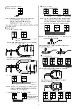


Connection of oil and gas balance pipes
Oil balance pipe
6.35
Gas balance pipe
15.9(flaring nut)
NOTE: See following chart for size T-shaped pipe X
connecting with oil pipe.
Connection of oil and gas balance pipes
1
16HP
capacity 24HP
NOTE: See following chart for size of Y-shaped
pipe A on liquid side:
Liquid pipe
19.0
Gas pipe
38.0
capacity
Liquid pipe
Gas pipe
Four modules
capacity
Liquid pipe 28.6
Gas pipe 67.0
Three modules
1
32HP
capacity
48HP
Liquid pipe
25.0
Gas pipe
54.0
12.7(
15.9)
28.6(
38.0)
12.7(
15.9)
28.6(
38.0)
19.0(
22)
38.0(
45.0)
<Module installation chart>
Single module
Gas pipe
Liquid pipe
NOTE: Pipe size of model 8HP, 10HP and 12HP:
liquid side
12.7, gas side
28.6.
Pipe size of model 14HP and 16HP:
liquid side
15.9, gas side
38.0.
Gas and oil balance pipes should be sealed by welding
for single module.
Two modules
See following chart for size of Y-shaped
pipe B on gas side:
See following chart for size of Y-shaped
pipe D on gas side:
NOTE: See following chart for size of Y-shaped
pipe C on liquid side:
NOTE: Wrap the valves
with wet cloth when welding,
or the valves may be
damaged to cause leakage.
NOTE: The size of Y-shaped pipes A and B on liquid
side and gas side respectively are the same
with that specified in item(1).
Oil balance pipe 6.35
NOTE: The size of Y-shaped pipes A and B on liquid
side and gas side respectively are the same
with that specified in item(1) of two modules.
Oil balance pipe 6.35
Connection of oil and gas balance pipes
See following chart for size T-shaped pipes Y and Z
connecting with gas pipe.
Gas balance pipe
19.0(welding)
Gas balance pipe
15.9(flaring nut)
Gas balance pipe
19.0(welding)
X
Y
Z
Y
Z
3-
15.9
3-
19.0
Gas balance pipe
15.9(flaring nut)
Gas balance pipe
19.0(welding)
X
Y
Z
X
Y
Z
Содержание MDV-D Series
Страница 12: ......


