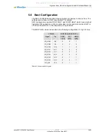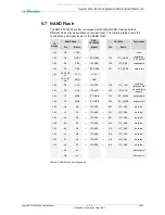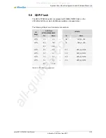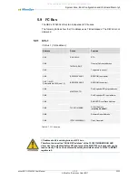
Peripherals 6
miriac SBC-LS1043A2 User Manual
V 2.2
37/72
© MicroSys Electronics GmbH 2017
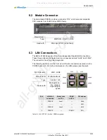
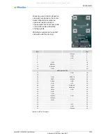
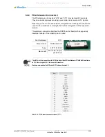
The LAN Sockets have a standard layout for GBit Ethernet, i.e. the pairs are 1-2, 3-
6, 4-5 and 7-8.
Pin
Pair
1
D-A+
2
D-A-
3
D-B+
4
D-C+
5
D-C-
6
D-B-
7
D-D+
8
D-D-
Table 6-3 LAN Gigabit Ethernet connector pairs
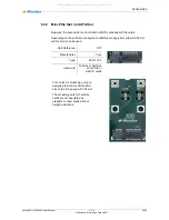
6.3.1 Port 1
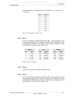
Port 1 is connected to a standard RJ-
45 socket “LAN1”. It uses the SerDes Lanes 1
provided by the LS1043A CPU configured as SGMII port. The SGMII lanes connect
to a Marvell PHY 88E1512P which uses a copy of the reference voltage on pin T80
of the module connector ST4 as I/O voltage (1.8V).
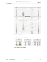
88E1512P
ST4
LS1043A
Pin
Name
Pin
Signal
Pin
Name
1
S_INP
←
T41
SRD-TX1+
←
AD6
SD1-TX0
2
S_INN
←
T42
SRD-TX1-
←
AE6
SD1-TX0#
4
S_OUTP
→
T38
SRD-RX1+
→
AG6
SD1-RX0
5
S_OUTN
→
T39
SRD-RX1-
→
AH6
SD1-RX0#
Table 6-4 SerDes 1 pin assignment
6.3.2 Port 2
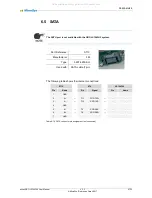
Port 2 is not connected on the SBC-LS1043A2 system.
6.3.3 Port 3
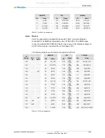
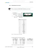
Port 3 is connected to a standard RJ-
45 socket “LAN2”. It uses the SerDes Lanes 3
provided by the LS1043A CPU configured as SGMII port. The SGMII lanes connect
to a Marvell PHY 88E1512P which uses a copy of the reference voltage on pin T80
of the module connector ST4 as I/O voltage (1.8V).
All manuals and user guides at all-guides.com

