System Core, Boot Configuration and On-Board Memory 5
miriac SBC-LS1043A2 User Manual
V 2.2
29/72
© MicroSys Electronics GmbH 2017
5.6
Boot Configuration
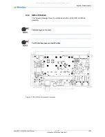
The SBC-LS1043A2 board offers three possible boot devices to choose from. The
settings can be done via SW1 (see chapter 7 for details).
SW1 configur
es two signals “BOOT-SEL1” and “BOOT-SEL2” which have a default
high state (10k pullups are on the module) when no connection is made or SW1 is
off. When the switch is on, the respective pin is grounded.
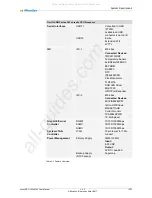
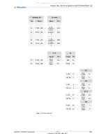
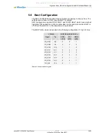
The BOOT-SELx pins are decoded to the following configuration (1= high, 0=low):
LS1043A
BOOT-SEL2 | BOOT-SEL1 =
Signal
Pin
SDHC
=[10]
SPI
=[11]
NAND
=[01]
IFC_AD08
B9
0
0
1
IFC_AD09
A9
0
0
0
IFC_AD10
A10
1
1
0
IFC_AD11
B11
0
0
0
IFC_AD12
A11
0
0
0
IFC_AD13
B12
0
0
0
IFC_AD14
A12
0
1
1
IFC_AD15
A13
0
0
1
IFC_CLE
F16
0
1
1
Table 5-4 Hard wired boot signals
All manuals and user guides at all-guides.com


