background image

PolarFire Dual Camera Video Kit

Microsemi Proprietary DG0849 Demo Guide Revision 1.0

6

2.

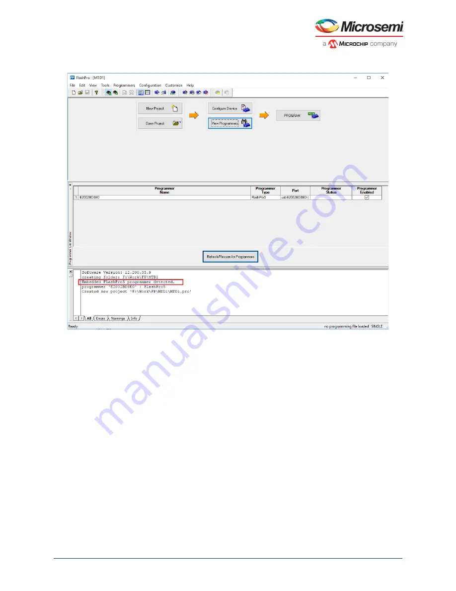
Verify that the FlashPro5 programmer is detected and displayed as shown in the following figure.

Figure 3 • 

View Programmer

3.

Select 

File

 -> 

Run script

. The Execute Script dialog box opens as shown in the following figure.

Содержание DVP-102-000512-001

Страница 1: ...DG0849 Demo Guide PolarFire Dual Camera Video Kit ...

Страница 2: ...mi It is the Buyer s responsibility to independently determine suitability of any products and to test and verify the same The information provided by Microsemi hereunder is provided as is where is and with all faults and the entire risk associated with such information is entirely with the Buyer Microsemi does not grant explicitly or implicitly to any party any patent rights licenses or any other...

Страница 3: ...story 1 1 1 Revision 1 0 1 2 PolarFire Dual Camera Video Kit 2 2 1 Design Requirements 3 2 2 Prerequisites 3 2 3 Demo Resources 3 2 4 Installing the Demo GUI 4 2 5 Setting Up the Demo 4 2 5 1 Setting Up the Hardware 4 2 5 2 Programming the PolarFire Device 5 2 6 Running the Demo 9 ...

Страница 4: ...e 3 View Programmer 6 Figure 4 Running Script 7 Figure 5 Run Passed Notification 8 Figure 6 Video_Contol GUI 9 Figure 7 FlashPro5 COM Port 9 Figure 8 Connecting the GUI and Video kit 10 Figure 9 Connection Successful 10 Figure 10 Adjusting Contrast and Brightness 11 Figure 11 Adjusting Colors 11 Figure 12 Edge Detection Option 12 Figure 13 PIP Menu 12 ...

Страница 5: ...Microsemi Proprietary DG0849 Demo Guide Revision 1 0 v Tables Table 1 Design Requirements 3 Table 2 Jumper Settings 4 ...

Страница 6: ...uide Revision 1 0 1 1 Revision History The revision history describes the changes that were implemented in the document The changes are listed by revision starting with the most current publication 1 1 Revision 1 0 The first publication of this document ...

Страница 7: ...nts such as contrast brightness color balance Note The solution includes a user friendly GUI used to control these image video settings The PolarFire Video Kit DVP 102 000512 001 features A 300K LE FPGA MPF300T FCG1152 HDMI 1 4 transmitter ADV7511 chipset and corresponding connector HDMI 2 0 with rail clamps and redrivers and corresponding connectors Dual camera sensor featuring IMX334 Sony image ...

Страница 8: ...wing resources A programming file STP file This file is the FPGA bitstream to be programmed A binary file BIN file for the on board SPI flash This file is the user application that is executed by the Mi V soft processor in the FPGA The file is stored in SPI flash and is used to initialize the fabric RAMs at device power up A TCL script file This script stores the TCL instructions to program the Po...

Страница 9: ...le with the PolarFire Video Kit and verifying the jumper settings The following steps describe how to connect the camera module to video kit 1 Connect the J1 connector of the dual camera sensor module to J38 interface of the video kit 2 Connect the video kit and the HDMI monitor through J2 HDMI 1 4 of the video kit using the HDMI cable 3 Connect the Host PC and the video kit through J12 of the vid...

Страница 10: ...are is set up See the next section to program the PolarFire device 2 5 2 Programming the PolarFire Device The TCL script is used to program the PolarFire device The FlashPro software can execute the TCL script file Follow these steps 1 Open FlashPro and create a new project as shown in the following figure Figure 2 Creating New Project ...

Страница 11: ...ry DG0849 Demo Guide Revision 1 0 6 2 Verify that the FlashPro5 programmer is detected and displayed as shown in the following figure Figure 3 View Programmer 3 Select File Run script The Execute Script dialog box opens as shown in the following figure ...

Страница 12: ...4 Use the Browse option to select the Script tcl file from the following design files folder script file location Note In the TCL file ensure that the path separator is replaced with when using a Windows PC 5 Select Run to run the script Once complete a message appears in the log as shown in the following figure ...

Страница 13: ...etary DG0849 Demo Guide Revision 1 0 8 Figure 5 Run Passed Notification The PolarFire device and SPI Flash are programmed Power cycle the board using switch SW4 The camera feed from the 2 cameras is displayed on the HDMI monitor as Picture in Picture ...

Страница 14: ... Video_Control GUI and then observing the result on the HDMI monitor To use the demo GUI 1 Start the Video_Control GUI from the installation directory The GUI is displayed as shown in the following figure Figure 6 Video_Contol GUI 2 Note the FlashPro5 COM port from Device Manager Figure 7 FlashPro5 COM Port 3 Select the same FlashPro5 COM port on the GUI and select the Connect option ...

Страница 15: ...ra Video Kit Microsemi Proprietary DG0849 Demo Guide Revision 1 0 10 Figure 8 Connecting the GUI and Video kit 4 The connect button turns green to indicate that the connection is successful Figure 9 Connection Successful ...

Страница 16: ...re highlighted in the following figure Figure 10 Adjusting Contrast and Brightness 6 Similarly adjust the color balance of the image using the color balance sliders Figure 11 Adjusting Colors 7 Similarly adjust the Alpha slider The alpha blending feature enables adjusting the transparency of the PIP image When the alpha value is adjusted to minimum 0 the image disappears 8 Switch to edge detection...

Страница 17: ... PIP Menu the source of the PIP window can be selected between Camera 1 and Camera 2 using PIP Source Select The position of the PIP window can be moved anywhere within the screen by dragging it The Auto Mode Start option moves the PIP window automatically The speed of this movement can be controlled using the Auto Mode Step slider Figure 13 PIP Menu This concludes the demo ...

Отзывы: