background image

Tigercat System Board Manual

Chapter 3: Installing the Tigercat

29

CPU Installation

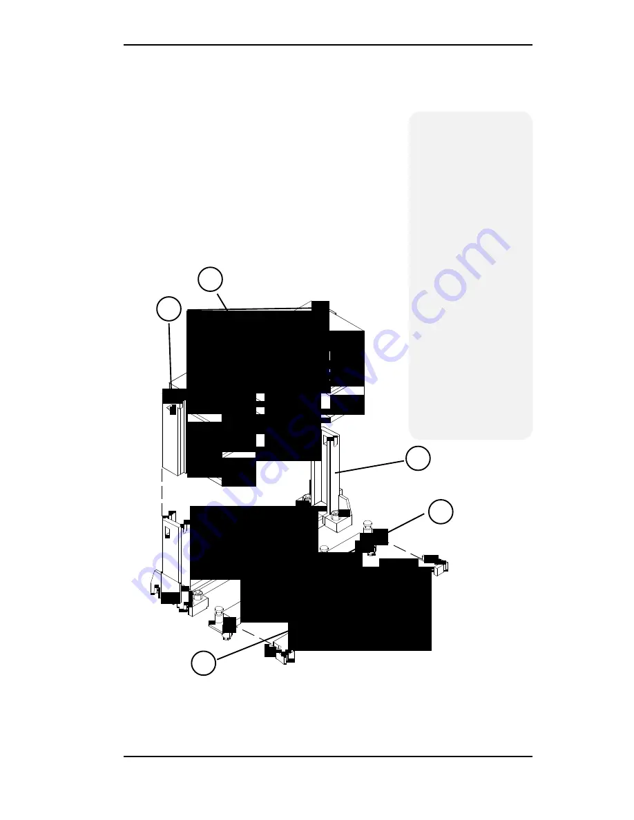
Overview

1. Mount the Retention

Mechanism for the

CPU.

2. Mount the (optional)

heatsink support base

onto the system board.

3. Slide the CPU into the

Retention Mecha-

nism.

4. Lock the CPU into the

Retention mechanism

using the tabs.

5. Slide in the  Heat Sink

Top Bar, then insert

the pins to lock it in

place.

5

1

2

3

4

CPU Installation Overview

Figure 3-2: Installing a CPU

Содержание Tigercat

Страница 1: ...Tigercat Pentium II System Board Manual Document Number 06 00305 01 Rev 2A July 1997 45365 Northport Loop West Fremont CA 94538 6417...

Страница 2: ...to this document and or product at any time and without notice All Rights Reserved No part of this document may be photocopied reproduced trans lated or reduced to any medium or machine form without...

Страница 3: ...onsiderations 11 Tigercat System Board 12 Tigercat Back Panel Connections 12 Jumper Settings 13 Chapter 3 Installing the Tigercat 19 Introduction 19 System Memory Support 19 Installing the Tigercat 20...

Страница 4: ...itial Bootup 37 Setup 37 Running the Setup Procedure 39 Setting the Main Screen 39 Setting the Advanced Screen 44 Security Screen 47 Power Screen 50 Boot Screen 52 Exit Screen 53 Chapter 5 Installing...

Страница 5: ...pendix B Post Messages 63 Appendix C Beep and POST Codes 65 Appendix D Hard Disk Drive Types 69 Appendix E Updating the System BIOS 71 Appendix F Warranties and Notices 73 Limited Warranty 73 FCC Stat...

Страница 6: ...38 Figure 4 2 CMOS Main Screen 39 Figure 4 3 IDE Device Submenu 42 Figure 4 4 Advanced Screen 44 Figure 4 5 Security Screen 47 Figure 4 6 Supervisor Password Submenu 48 Figure 4 7 Power Screen 50 Fig...

Страница 7: ...on the Tigercat comes with an AGP Acceler atedGraphicsPort busslot afaster busthanthecurrent 33MHz PCI bus The AGP bus provides a direct connec tionbetweenthegraphicssubsystemandsystemmemory The Wake...

Страница 8: ...r 32 bit PCI slots Two 16 bit ISA slots One is a shared PCI ISA slot One AGP slot Four 3 3V unbuffered 64 bit 168 pin DIMM sockets Maximum memory 512MB for SDRAM Maximum memory 1GB for EDO Supports ED...

Страница 9: ...roughly tested for compatibility with a variety of operating systems and envi ronments including Microsoft DOS 6 2x Windows 95 Windows NT 3 5x Windows NT 4 0 IBM OS 2 Warp 3 0 OS 2 Warp 4 0 SCO UNIXWa...

Страница 10: ...gnifying Glass it refers to something you should take a closer look at before proceeding further When you see the Exclamation Mark it gives important information on avoiding damage Common Names AGP Ac...

Страница 11: ...Chapter 2 5 Install the CPU and the system memory Be sure to attach the Retention Mechanism as described in Chapter 3 6 Install the system board in the chassis and make all necessary case connections...

Страница 12: ...u have configured the Main Setup menu make any desired setting configurations in the Ad vanced and Security menu When finished go to the exitscreen select SaveChangesandExit andyouare finished with th...

Страница 13: ...a special anti static wrist or ankle strap If you do not have an anti static strap available touch both of your hands to a safely grounded object such as the power supply or chassis of a computer that...

Страница 14: ...Board Manual Tigercat System Board Tigercat Back Panel Connections Chapter 2 Configuring the Tigercat 12 Figure 2 1 Tigercat System Board Diagram Figure 2 2 Back Panel Connections Intel Venus I O Shi...

Страница 15: ...ngs Any changes you have made will be lost Table 2 1 System Speed Selection Table 2 2 Clear CMOS Settings r e p m u J n o i t c n u F s g n i t t e S 5 W t l u a f e d l a m r o N S O M C r a e l C 2...

Страница 16: ...s which include the CPU and the 440LX chipset Pipelining allows for the overalltaskofthesedevicestobedividedintosmalleroverlappingtasks and provides fast throughput for sequential processes Table 2 5...

Страница 17: ...ce a jumper on W4 in position 2 3 as shown in the table Refer to Appendix E for details on reprogramming the system BIOS Table 2 7 Onboard Sound Wavetable Selection Table 2 8 Flash Memory Setting r e...

Страница 18: ...S P l e v e L r e w o L l e v e L r e p p U 3 1 J r o t c e n n o C t r o P l e l l a r a P l e v e L r e p p U 5 1 J 4 1 J s t r o P l a i r e S B M O C A M O C 9 1 J 6 1 J s t o l S n o i s n a p x...

Страница 19: ...3 3 J n I e n i L o i d u A D C d n u o r G 2 l e n n a h C t f e L n I e n i L 1 l e n n a h C t h g i R n I e n i L 4 d n u o r G 3 4 3 J d n u o S o i d u A M O R D C e c a f r e t n I r e t s a l...

Страница 20: ...Tigercat System Board Manual Chapter 2 Configuring the Tigercat 18...

Страница 21: ...ponents may void the warranty If prob lems arise while installing peripherals contact the computer dealer where you purchased the peripheral or Micronics Technical Support Department System Memory Sup...

Страница 22: ...onics recommends using the following tools to install the Tigercat Small Phillips screwdriver Tweezers or a pair of needle nose pliers Tray to hold loose screws Equipment Required Micronics recommends...

Страница 23: ...s a list of rules to follow when installing DIMMs If you follow these rules your upgrade should be trouble free Use 10ns or faster SDRAM or 60ns or faster EDO DIMMs DIMM memory modules support EDO and...

Страница 24: ...configurations Memory Bank 1 Bank 2 Bank 3 Bank 4 8MB 1Mx64 16MB 2Mx64 16MB 1Mx64 1Mx64 24MB 2Mx64 1Mx64 24MB 1Mx64 1Mx64 1Mx64 32MB 2Mx64 2Mx64 32MB 4Mx64 32MB 1Mx64 1Mx64 1Mx64 1Mx64 40MB 2Mx64 2Mx6...

Страница 25: ...Mx64 1Mx64 1Mx64 80MB 8Mx64 2Mx64 80MB 8Mx64 1Mx64 1Mx64 96MB 4Mx64 4Mx64 2Mx64 2Mx64 96MB 4Mx64 4Mx64 4Mx64 96MB 8Mx64 2Mx64 1Mx64 1Mx64 112MB 4Mx64 4Mx64 4Mx64 2Mx64 112MB 8Mx64 4Mx64 2Mx64 112MB 8M...

Страница 26: ...8Mx64 8Mx64 8Mx64 224MB 16Mx64 8Mx64 2Mx64 2Mx64 224MB 16Mx64 8Mx64 4Mx64 256MB 16Mx64 16Mx64 256MB 16Mx64 8Mx64 4Mx64 4Mx64 256MB 16Mx64 8Mx64 8Mx64 256MB 8Mx64 8Mx64 8Mx64 8Mx64 288MB 16Mx64 16Mx64...

Страница 27: ...h the notch on the DIMM socket Figure 3 1 2 Insert the DIMM at a 90 degree angle 3 Gently push the DIMM straight down until it locks into place past the release tabs Figure 3 1 Installing a 168 Pin DI...

Страница 28: ...oard AttachtheRetentionMecha nism before inserting the processor Installing the CPU Retention Mechanism Before you begin verify that your Retention Mechanism Kit contains the following items Retention...

Страница 29: ...se 3 Using a screwdriver tighten all four sides of the Retention Base Installing a CPU FollowthestepsbelowtoinstallthePentiumIIprocessor 1 Locate the Slot 1 connector refer to Figure 2 1 2 Ifyouareins...

Страница 30: ...ge 6 Push the processor cartridge down until it snaps into place 7 Lock the processor cartridge into place by pushing outward on the tabs located on both sides of the processorcartridge Theprocessorca...

Страница 31: ...Mechanism for the CPU 2 Mount the optional heatsink support base ontothesystemboard 3 SlidetheCPUintothe Retention Mecha nism 4 LocktheCPUintothe Retentionmechanism using the tabs 5 Slideinthe HeatSin...

Страница 32: ...s packaging uses an active cooling fan The mounting hardware is described below For detailed instructions please refer to the documentation that is supplied with your CPU NOTE Make sure the speed sele...

Страница 33: ...f and remove its cover 2 Choose an unused PCI slot and remove the slot cover 3 Insert the card with the bottom edge level to the slot Never insert the card at an angle 4 Carefully push the card straig...

Страница 34: ...cover 2 Choose an unused ISA slot and remove the slot cover 3 Insert the card with the bottom edge level to the slot Never insert the card at an angle 4 Carefully push the card straight down making su...

Страница 35: ...AGP slot J1 and remove the slot cover 3 Insertthecardwiththebottomedgeleveltotheslot Never insert the card at an angle 4 Carefully push the card straight down making sure the card is fully inserted 5...

Страница 36: ...umentation making sure the red stripe on the cable is aligned with pin 1 of the connectors 2 Connect the audio cable to the CD ROM drive s audio connector 3 Connect the other end of the audio cable to...

Страница 37: ...oard to take advantage of the optional sound support refer to Figure 2 2 The sound option includes 16 bit stereo sound and a game and MIDI port See Chapter 5 for information on installing sound device...

Страница 38: ...ut The Line Out jack allows you to connect the audio outputoftheaudiocontrollertoyourhomestereo VCR or amplified speakers Line In You may connect an external mono or stereo audio source to the audio c...

Страница 39: ...r cables and peripherals for bad connections You may also get beep codes or error messages If this occurs consult Appendix B for a guide to possible solutions After the system properly boots it is rea...

Страница 40: ...d on your monitor as shown in Figure 4 1 Figure 4 1 Power Up Screen When Press F2 to enter Setup appears at the bottom of the screen press the F2 key to start the Setup program The main CMOS Setup uti...

Страница 41: ...d Exit To toggle between the screens press the right arrow and the left arrow keys Setting the Main Screen The CMOS Main screen is used to set the time and date to set the floppy drive types to config...

Страница 42: ...ethe keystochange the setting until it matches the floppy drive you installed The BIOS supports 2 88MB 1 44MB 1 2MB 720KB and 360KB floppy drives Numlock SettingthistoON activatesNumlockuponboot Setti...

Страница 43: ...OS into RAM for faster execution To disable the System BIOS category select Disabled System Memory The System Memory category identifies the size of the base memory It cannot be changed Extended Memor...

Страница 44: ...information may be in the manual which came with your system If not contact your dealer or the hard drive manufacturer to fill in this category If you are using a SCSI hard drive select None and refe...

Страница 45: ...your drive will not run at this speed The default setting is Disabled Transfer Mode This category sets the transfer speeds for IDE devices The Standard option is the default setting The Fast PIO 1 Fa...

Страница 46: ...ow Figure 4 4 Advanced Screen Serial Port A Serial Port A may be configured using the following options Disabled No configuration Enabled User configuration Auto BIOS configuration and PnP O S O S con...

Страница 47: ...r Disabled Integrated Sound Card Enables or disables the integrated sound interface The optionworksonlyifyoursoundcardhasbeenenabledvia the jumper refer to Chapter 2 The default setting is Enabled LM7...

Страница 48: ...ice must still have and load its own drivers for thatparticularoperatingsystem SelectEnabled default when using DOS and Windows 95 operating systems Select Disabled when using Windows NT OS 2 and Unix...

Страница 49: ...ECC x72 this selection can be set for Error Checking Error Checking and Correction or Checking Connection with Scrub bing The default setting is Disabled Security Screen The Security screen controls a...

Страница 50: ...appears Type the password and press the ENTER key Retype the password and press the ENTER key again Write down the password somewhere safe so it will not be forgotten The password may be disabled by s...

Страница 51: ...may be entered Fixed Disk Boot Sector This selection allows the boot sector of the fixed disk to be write protected The default setting is Normal When set for Write Protected it serves as a form of v...

Страница 52: ...the up and down arrow keys Figure 4 7 Power Screen Power Savings This selection allows you to change the system power management settings Maximum Power Savings con serves the greatest amount of system...

Страница 53: ...options are Off default 5 min 10 min 15 min 20 min 30 min 40 min or 60 min Before making changes Customized must be selected in the Power Manage ment Mode selection Resume On Time When this feature is...

Страница 54: ...ve between the categories use the up and down arrow keys Figure 4 8 Boot Screen Boot Device Priority This feature will set the search order for the types of bootable devices Hard Drive This selection...

Страница 55: ...configuringtheBIOS selecttheExit screen To move to the Exit Screen use the left and right arrow keys until it appears To move between the categories use the up and down arrow keys Figure 4 9 Exit Scre...

Страница 56: ...Tigercat System Board Manual Chapter 4 The BIOS Setup Utility 54...

Страница 57: ...r system Usually a device driver is added to the CONFIG SYS file the AUTOEXEC BAT file or both Installing the Sound Drivers Once you have connected your external sound devices you can install the soun...

Страница 58: ...er s manual for instructions on how to install sound drivers 7 If you are using Windows NT refer to the Windows NT user s manual for instructions on how to install sound drivers 8 If you are using OS...

Страница 59: ...ra I O chip Form Factor ATX footprint Four layer board Stacked I O connectors Intel Venus I O Shield compatible 20 pin ATX power connector Expansion Four 32 bit PCI slots Two 16 bit ISA slots One is a...

Страница 60: ...header ATAPI 4 pin Line In header ATAPI Built in wavetable synthesis Sound drivers Hardware LM78 Microprocessor System Hardware Monitor Management LM75 CPU Temperature Sensor I O Ports Two high speed...

Страница 61: ...is critical Micronics recommends the following environmental specifica tions Temperature Range Operating 50 to 104 degrees Fahrenheit 10 to 40 degrees Celsius Non Operating 50to140degreesFahrenheit 1...

Страница 62: ...ppendix A Technical Information Battery Disposal WARNING Please do not open battery dispose of in fire recharge put in backwards or mix with used or other battery types The battery may explode or leak...

Страница 63: ...Technical Support If you need technical assistance our Technical Support Engineers will be glad to help you You can contact us via telephone fax or BBS Before calling Technical Support please have th...

Страница 64: ...n protocols 44 1256 363373 RMA Return Materials Authorization Return products for repair M F 8 00am to 4 45pm PST USA 510 661 3030 510 683 0543 Fax Fax On Demand Automated system for product literatur...

Страница 65: ...X FAILURE where X 0 or 1 The hard disk is not configured or working properly Rerun SETUP and check connections or replace hard disk FIXED DISK CONTROLLER FAILURE The controller card has failed Check c...

Страница 66: ...ECK 2 nnnn Parity error found in the I O bus Check Setup Board repair may be required PREVIOUS BOOT INCOMPLETE DEFAULT CONFIGURATION USED Previous POST did not complete successfully Run Setup load def...

Страница 67: ...gth of the pauses between the beeps varies For example a 1 3 3 beep code will sound like one beep a pause three beeps consecutively another pause and then three more beeps One beep code is often misun...

Страница 68: ...tial POST values 12 Jump to UserPatch0 14 Initialize keyboard controller 16 2 2 3 BIOS ROM checksum 18 8254 timer initialization 1A 8237 DMA controller initialization 1C Reset Programmable Interrupt C...

Страница 69: ...nded memory 62 Test extended memory address lines 64 Jump to UserPatch1 66 Configure advanced cache registers 68 Enable external and CPU caches 6A Display external cache size 6C Display shadow message...

Страница 70: ...B6 Check password optional B8 Clear global descriptor table BC Clear parity checkers BE Clear screen optional BF Check virus and backup reminders C0 Try to boot with INT 19 D0 Interrupt handler error...

Страница 71: ...7 21 7 462 8 256 17 32 8 733 5 none 17 31 9 900 15 none 17 117 10 820 3 none 17 21 11 855 5 none 17 37 12 855 7 none 17 52 13 306 8 128 17 21 14 733 7 none 17 44 15 N A N A N A N A N A 16 612 4 0 17 2...

Страница 72: ...k Drive Types Type Cylinders Heads Write Precomp Sectors Size 31 823 10 512 17 71 32 809 6 128 17 42 33 830 7 none 17 50 34 830 10 none 17 72 35 1024 5 none 17 44 36 1024 8 none 17 71 37 615 8 128 17...

Страница 73: ...he system has rebooted the cursor will appear at the A prompt 4 NowyoucanruntheFLASHutilityfromthebootable floppy disk Refer to the README TXT file in cluded with the BIOS update for detailed instruc...

Страница 74: ...Tigercat System Board Manual Appendix E Updating the System BIOS 72...

Страница 75: ...xcessive or inad equate heating or air conditioning or electrical power failures surges or other irregularities 4 any statement about the product other than those set forth in this warranty or 5 nonco...

Страница 76: ...rofits or any indirect special incidental or consequential damages in connection with the product even if Micronics has been advised of the possibility of such damages Micronics makes no warranties or...

Страница 77: ...l interference to radio communications Interfer ence to radio or television reception can be determined by turning the equipment off and on You are encouraged to try to correct the interference by one...

Страница 78: ...e buffer logic chips on their control lines to reduce loading on the system board This buff ering action increases the maximum Glossary Glossary 76 number of modules on the same sys tem board The buff...

Страница 79: ...a bits present ECP An acronym for Expanded Capabilities Port A standard set by Hewlett Packard and Microsoft Corpo ration to expand the capabilities of the parallel port EDO Memory An acronym for Ex t...

Страница 80: ...rity bit is used for each byte 8 bits of data The most commonly used forms of parity are even parity odd parity and checksums PCI An acronym for Peripheral Com ponent Interconnect A high perfor mance...

Страница 81: ...IMM modules do not use any buffer logic chips thus achieving faster opera tion due to the elimination of the propagation delay of the logic buffer This increase in speed comes at the cost of reducing...

Страница 82: ...System BBS 62 C Configuring the Tigercat 11 CPU Box Version 30 Installation 20 Overview 29 30 Retention Mechanism 26 D Diagram Tigercat 12 E Extended Data Out EDO Memory 19 21 Environmental Specificat...

Страница 83: ...heral Card 33 ISA Peripheral Card 32 PCI Peripheral Card 31 Quick Installation 9 J Jumper Settings 13 M Tigercat System Board Diagram 12 Memory Configurations 22 Installing 25 Removing 25 Supported 21...

Страница 84: ...7 Technical Support 61 Troubleshooting 63 65 U Updating the System BIOS 71 Utility Programs Utility Programs Advanced Screen 44 BIOS Setup 37 Boot Screen 52 Exit Screen 53 IDE Device Submenu 42 Main S...

Отзывы: