


10
Step 10:
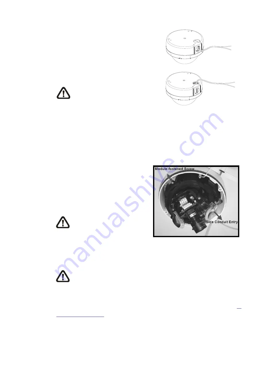
Thread the power and Ethernet
cables through either the Side
Conduit Entry or Back Conduit Entry,
as illustrated. Users may use a coin
to screw off the Conduit Entry Block.
NOTE:
The Power Cable is
omitted if using PoE.
Step 11:
Connect the power and Ethernet
cables to the mating connectors on
the Camera Module.
Step 12:
Attach the Snap-on Camera Module
into the Dome Camera Housing, and
screw the Module-fastened Screw
tightly to secure the camera module.
NOTE:
The terminal blocks
should face the Side Conduit
Entry, as shown in the figure.
Step 13:
Connect the power and network outputs.
NOTE:
The Power Cable is omitted if using PoE.
STEP 14:
Access the Camera Browser-viewer for viewing images. Please refer to
6.
Accessing Camera
for further details. Users can also use the Camera’s
BNC Connector for video output.
Содержание SP5582HTM
Страница 1: ...Micronet SP5582HTM Micronet SP5582HTM Full HD Vandal Dome IP Camera User Manual Ver1 0 ...
Страница 7: ...6 2 2 Connectors ...
Страница 20: ...19 The popup window for confirmation will come out as shown below Click Yes to start deleting the files ...
Страница 31: ...30 ...
Страница 52: ...51 Password Key Enter the password or key required by the DDNS provider for authentication ...
Страница 63: ...62 ...
Страница 79: ...78 6 3 17 View Parameters Click on this item to view the entire system s parameter setting ...
Страница 96: ...95 Type Select to change the mask type as solid or transparent Click Save to confirm the setting ...
Страница 113: ...112 Step 3 Click Finish to close the DC Viewer installation page Then the camera s Home page will display as follows ...
Страница 116: ...115 Step 5 Click Next in the Windows Components Wizard page Step 6 Click Finish to complete installation ...


