5
Microframe Corporation
Series 5100 Information
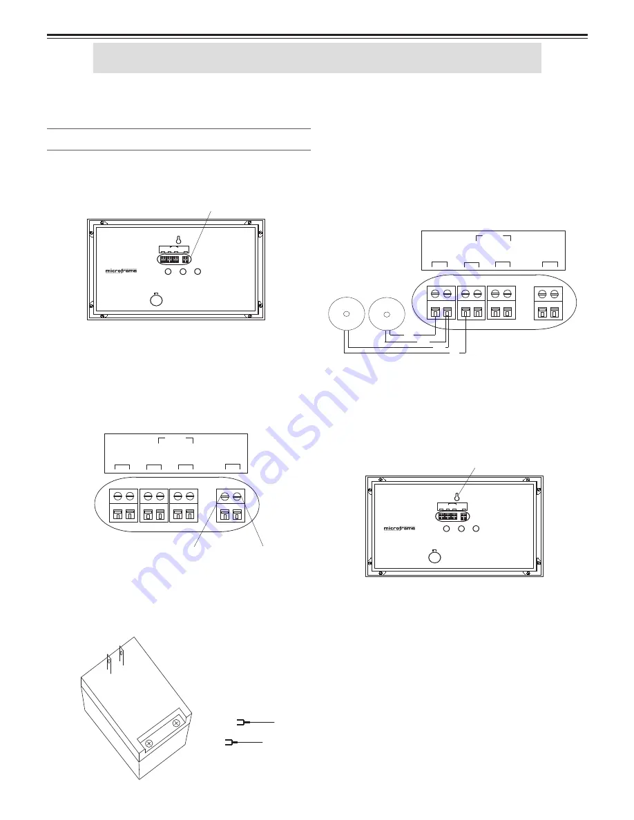
Microframe Corporation
Step 3: Push Buttons
***Please Note***
Only connect the push button
wires to the screwdown terminals when the power to
the display is "OFF."
From the provided wire, cut to length two pieces of
wire, one for each button. For each wire, connect one end
to a brass push button. Place the two black conductors
(one from each wire) under the terminal labeled "com-
mon." Put the red conductor from one wire under the
"Input 1" terminal. Put the remaining red wire from
the other wire under the input 2 terminal.
Step 4: Hanging Display
The display is manufactured to hang on the wall like
a picture. For aesthetic purposes, you may wish to run
the wiring in a wall or raceway.
Step 5: Powering the Display
Plug the power adapter into an AC outlet. The dis-
play LEDs should now be illuminated and show numeric
characters. The system is now operational.
***Please Note***
To avoid damaging this product,
please disconnect power before performing any service.
To ensure proper disconnection, the power adapter must
be unplugged from the AC outlet.
5100 Display Installation Procedures
Step 1: Screwdown Connectors
All wire connections to Microframe displays are made
with screwdown terminals located on the back of the
display.
Step 2: Connecting Power
To connect power to the "24VAC terminal," fi rst loosen
the terminal's screw. Then push the stripped end of the
power adapter wire into the opening in the side of the
terminal. Tighten the screw onto the wire. Check that the
wire is secure in the terminal by lightly pulling on it.
To connect the power adapter wire to the wall mounted
transformer, fi rst loosen the screwdown terminals. Next,
slide one spade connector under each terminal. Lastly,
tighten each screw onto the spade connectors.
Getting Started
CO
M
MO
N
B
A
IN
P
UT
2
24V
AC
IN
P
UT
1
485
CO
M
M
5100\PX\9803.ai
adapter wire 1
adapter wire 2
INPUT 1
IN
TE
RNAL
CHI
M
E
Model 5100 Display
SELECT
COMMON
B A
INPUT 2
24V
AC
485
COMM
5100\PX\9802.ai
MODE
ADVANCE
screwdown terminals
INPUT
1
IN
TE
RNAL
CHI
M
E
Model 5100 Display
SELECT
CO
M
MON
B A
INPUT
2
24V
AC
485
COMM
5100\PX\9802.ai
MODE
ADVANCE
mounting hole
CO
M
MO
N
B
A
IN
P
UT
2
24V
AC
IN
P
UT
1
485
CO
M
M
5100\PX\9803.ai
Red
Black
Black
Red
115
TO 2
4
VA
C
W
AL
L
MO
U
NT
E
D
TR
A
NS
FOR
M
ER
- - - - - - - - - -
- - - - - - - - - - - - -
The 5100 system is preset at the factory to work as a
Take-A-Number system. Simply make the connections
as described below, read the brief operating instructions,
and you should be ready to go.


