background image


MC2-30V


Doc. N°


MO-0499-ING


Copyright 2019 


Date 

17.03.2022


Rev. 

2


Pag. 

of 

63 


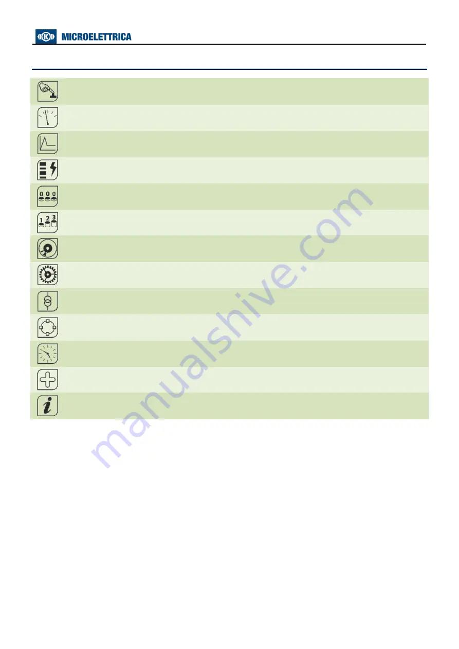
5. Icons of Display 


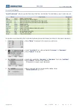
LocalCmd 

Local Commands 


Measure 

Actual Measurements 


Max Val. 

Maximum Values 


TripRec. 

Trip Recording 


Counter 

Partial Counters (Resettable Counter) 


ROCnt 

Total Counter (Read Only Counter) 


Events 

Event Recording 


Setting 

Function Settings  


System 

System Settings 


InfoStatus 

Information Status 


TimeDate 

Time And Date 


Healthy 

Diagnostic Information 


Dev.Info 

Relay Version 


Содержание MC2-30V

Страница 1: ...MC2 30V Doc N MO 0499 ING Copyright 2019 Date 17 03 2022 Rev 2 Pag 1 of 63 MICROPROCESSOR THREE PHASE VOLTAGE PROTECTION RELAY WITH ISLANDING DETECTION TYPE MC2 30V OPERATION MANUAL...

Страница 2: ...______________________________________________15 8 1 Name _____________________________________________________________________________________15 8 2 User Descr _______________________________________...

Страница 3: ...cription of variables __________________________________________________________________41 17 18 2 Operation ____________________________________________________________________________41 17 19 Functi...

Страница 4: ..._________________________________________________________________________________61 25 Wiring Diagram _________________________________________________________________________________62 26 Overall Dim...

Страница 5: ...racticable protection means used in designing electronic circuits the electronic components and semiconductor devices mounted on the modules can be seriously damaged by electrostatic voltage discharge...

Страница 6: ...ocal managemen USB for local communication Eight user programmable Output Relays Eight opto isolated self powered Digital Inputs RS485 communication port independent from the USB port on front panel 2...

Страница 7: ...e used to scroll the items of the different menus Local Control Measurements Energy metering etc Decrease By the key select the windows showing the ICONS of the available menus By the key select the d...

Страница 8: ...Actual Measurements Max Val Maximum Values TripRec Trip Recording Counter Partial Counters Resettable Counter ROCnt Total Counter Read Only Counter Events Event Recording Setting Function Settings Sys...

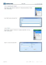
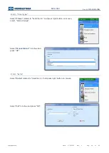
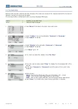
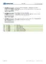
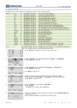
Страница 9: ...follows 1 Press Menu for access to the main menu with icons 3 Select LedClear Press Select to execute the command 2 Select icon LocalCmd 4 When command has been executed the display shows Command Don...

Страница 10: ...of 63 7 Leds Configuration The relay manage up to 10 signal leds Programmable 1 led Power green For Leds programming only via software operate as follows Open the software program and connect to the r...

Страница 11: ...ed Flashing When cause appear led is flashing 7 5 Funct Mode Volatile When cause disappear led turn off Not memorized Latched When cause disappear led remain illuminated memorized 7 6 Functions Select...

Страница 12: ...1df dt Start First Frequency rate of change element 2df dt Start Second Frequency rate of change element tTCS Start Trip coil supervision IRF Start Internal Relay Failure tIRF Trip DskClean Disk near...

Страница 13: ...ched 1U Main Windows 7 8 1 Link Enable Select Link enable related to Led 1 and press right button on mouse select Value change Select Linked and press OK if Password is request see Password 7 8 2 Flas...

Страница 14: ...nct Mode related to Led 1 and press right button on mouse select Value change Select Latched and press OK if Password is request see Password 7 8 4 Functions Select Functions related to Led 1 and pres...

Страница 15: ...UP Fall Down 8 5 Timer Time delay 0 600 s step 0 01s 8 6 Timer type Delay Add a delay on output activation The Timer is edge triggered on rise edge Monostable P Activated the output for the time Time...

Страница 16: ...to UserVar 0 and press right button on mouse select Value change Insert Voltage Trip into box and press OK 8 9 2 Linked Functions Select Linked Functions related to UserVar 0 and press right button on...

Страница 17: ...3 Operation Logic Oplogic Select Oper Logic related to UserVar 0 and press right button on mouse select Value change Insert OR into box and press OK 8 9 4 Timer Select Timer related to UserVar 0 and...

Страница 18: ...g 18 of 63 8 9 5 Timer type Select Timer related to UserVar 0 and press right button on mouse select Value change Select Monostable P into box and press OK 8 9 6 Extra Select Extra related to UserVar...

Страница 19: ...Counter Clear Reset Counters Yes HistFail Clear Reset of Internal Failure Historic records Yes Leds Test Signal Leds test No Force Osc Force Oscillo Recording Yes Format iDisk Format internal disk Yes...

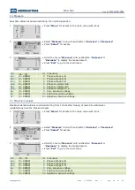
Страница 20: ...B C Uca 0 99999 V Phase to voltage C A Uo 0 99999 V Zero sequence voltage V1 0 99999 Vn Positive sequence voltage V2 0 99999 Vn Negative sequence voltage 11 Maximum Values Maximum demand values record...

Страница 21: ...ipRec icon with pushbutton Increase or Decrease Press Select for access 3 Select Display with pushbutton Increase or Decrease Press Select for access For Erase go to 8 4 If no trip is recorded the dis...

Страница 22: ...lect to execute the commands All Trips recorded are erased if Password is request see Password 9 When command has been executed the display shows Command Done Press Exit to go back to the main menu Fr...

Страница 23: ...ations counters Trip Circuit Supervision IRF 0 Operations counters Internal Relay Fault BrkF 0 Operations counters Breaker failure AutOp 0 Operations counters Automatic C B Opening AutCL 0 Operations...

Страница 24: ...ent U2 0 Operations counters Second Voltmetric unlock islanding detector element 1df dt 0 Operations counters First element df dt 2df dt 0 Operations counters Second element df dt TCS 0 Operations cou...

Страница 25: ...ess 3 Select Display with pushbutton Increase or Decrease Press Select for access For Erase go to 7 4 If no event is recorded the display shows message No Events 5 If any event was recorded select Vie...

Страница 26: ...se TimeSincro Time synchronization Rise Disk DskClean Disk near to full clean operation is required Rise DskFull Disk full write should be lock Rise L R disc Local Remote signal Discrepancy Rise rDskA...

Страница 27: ...the main menu with icons 2 Select System icon with pushbuttons Increase or Decrease Press Select for access 3 Select CTs PTs Press Select for access 4 Select PT Press Select for access 5 Select Primar...

Страница 28: ...management 1U First Overvoltage Element 2U Second Overvoltage Element 1U First Undervoltage Element 2U Second Undervoltage Element 1f First Overfrequency Element 2f Second Overfrequency Element 1f Fir...

Страница 29: ...ons Increase or Decrease 8 Set new values pushbuttons Increase or Decrease buttons Press Select Press Write 3 Select by pushbuttons Group 1 9 If the change of parameters is completed press Exit Press...

Страница 30: ...ease or Decrease to set the third digit 2 Press Next to validate and go to the next digit 6 Press Next to validate and go to the next digit 3 Use the key Increase or Decrease to set second digit 7 Use...

Страница 31: ...e interface program for Windows it is possible connect a Personal Computer to download all available information operate any control and program the relay the protocol used is Modbus RTU To avoid elec...

Страница 32: ...isplay backlight can be programmed always on ON or switched on Automatically for a few second set parameter tBckL at any operation of the keyboard Example set Local Language 1 Press Menu for access to...

Страница 33: ...ite policy on internal full disk condition StopWrite Write disable DelOldFiles Delete older folder and write 17 5 2 Download file informations Files related to Journal Fault log Oscillo are available...

Страница 34: ...ps_15 06 2016 txt Trips log File Trips_15 06 2016 txt Date Time Event Values 2016 06 15 08 17 27 200 tTCS Uab 0 0 Ubc 0 0 Uca 0 0 2016 06 15 10 31 03 901 tTCS Uab 0 0 Ubc 0 0 Uca 0 0 17 5 2 3 Oscillog...

Страница 35: ...Element F59 Status Enab No No Yes Oper Levels Us 90 Un 10 190 step 1 Timers ts 100 s 0 08 100 step 0 01 17 6 1 Description of variables Enab Function enabling No Disable Yes Enable Us Minimum operatio...

Страница 36: ...Element F27 Status Enab Yes No Yes Oper Levels Us 90 Un 10 190 step 1 Timers ts 100 s 0 08 100 step 0 01 17 8 1 Description of variables Enab Function enabling No Disable Yes Enable Us Minimum operati...

Страница 37: ...Enable Fs Minimum operation level ts Trip time delay 17 10 2 Operation Tripping of the function operates a user programmable output relay 17 11 Function 2f Second Overfrequency Element F81 Status Enab...

Страница 38: ...Enable Fs Minimum operation level ts Trip time delay 17 12 2 Operation Tripping of the function operates a user programmable output relay 17 13 Function 2f Second Underfrequency Element F81 Status Ena...

Страница 39: ...Enable Us Minimum operation level ts Trip time delay 17 14 2 Operation Tripping of the function operates a user programmable output relay 17 15 Function 2Uo Second Zero Sequence Overvoltage Element F5...

Страница 40: ...Enable Us Minimum operation level ts Trip time delay 17 16 2 Operation Tripping of the function operates a user programmable output relay 17 17 Function U2 Second Voltmetric unlock islanding detector...

Страница 41: ...dt Minimum operation level Ub Minimum voltage level 17 18 2 Operation Tripping of the function operates a user programmable output relay 17 19 Function 2df dt Second Frequency rate of change Element...

Страница 42: ...ntact of R1 is used to trip the C B as reported in the drawing here below The supervision works when the C B is closed and recognizes the Trip Circuit as sound as far as the current flowing exceeds 1m...

Страница 43: ...Start Trigger on time start of protection functions Trip Trigger on trip time delay end of protection functions OnCmd On Asynchronous Force trigger command REUserLg On rising edge of User Logic see Us...

Страница 44: ...nt t2f Trip 1Uo 1Uo Start t1Uo Trip 2Uo 2Uo Start t2Uo Trip U1 U1 Start tU1 Trip U2 U2 Start tU2 Trip 1df dt 1df dt Start 2df dt 2df dt Start TCS tTCS Start trip coil supervision IRF IRF Start Interna...

Страница 45: ...ons 17 22 4 4 OpLogic Operation Logic None OR AND XOR NOR NAND NOT Ff SR Counter Rise UP Fall Down 17 22 4 5 Timer Time delay 0 600 s step 0 01s 17 22 4 6 Timer type Delay Add a delay on output activa...

Страница 46: ...ay Select Change Windows from Menu button Select User Variable Setting for User Trigger Oscillo 1U 2U AND 1 Monostable 10 17 22 5 1 Linked Functions Select Linked Functions related to User Trigger Osc...

Страница 47: ...n Logic Oplogic Select Oper Logic related to User Trigger Oscillo and press right button on mouse select Value change Insert AND into box and press OK 17 22 5 3 Timer Select Timer related to User Trig...

Страница 48: ...2 5 4 Timer type Select Timer related to User Trigger Oscillo and press right button on mouse select Value change Select Monostable P into box and press OK 17 22 5 5 Extra Select Extra related to User...

Страница 49: ...The pushbuttons on Front Panel are disabled Enable The pushbuttons on Front Panel are Enable Key0 Configure a Key as C B Open KeyC Configure a Key as C B Close tL R Admissible time before detection o...

Страница 50: ...r 0 Gate 1 manOpCmd Gen Trip Manual Open Command Generic Trip UserVar 0 Gate 2 CL Cmd Close Command 17 21 2 3 DO Configuration Select DO Configuration Assign to Type Linked Functions 0 R1 Gate 1 0 R2...

Страница 51: ...ng diagram are shorted 0 D2 Programmable D2 0 D3 Programmable D3 0 D4 Programmable D4 0 D5 Programmable D5 0 D6 Programmable D6 0 D7 Programmable D7 0 D8 Programmable D8 18 2 DI Configuration via soft...

Страница 52: ...on function 18 2 5 Example Setting Digital Input Open software program and connect to the relay Select Change Windows from Menu Select DI configuration Setting for Bi1U 1U 18 2 5 1 Functions Select Fu...

Страница 53: ...1 Relay Relay internal name 18 4 1 2 Linked function It s available only 1 link select the function for tripping the output relay for multiple association use User Variable 18 4 1 3 Operation Logic N...

Страница 54: ...the output relay is operated when the controlling Functional Output is activated and remains in the operated condition until a manual reset command is issued by the relay keyboard local commands menu...

Страница 55: ...ings for 0 R1 Change settings for 0 R1 1U Normally Denergized Automatic reset 0 5 18 4 2 2 Linked Functions Select Linked Functions related to 0 R1 and press right button on mouse select Value change...

Страница 56: ...9 Date 17 03 2022 Rev 2 Pag 56 of 63 18 4 2 3 Output Config Select Output Config related to 0 R1 and press right button on mouse select Value change Select Normally Denergized from combo box and press...

Страница 57: ...tion related to 0 R1 and press right button on mouse select Value change Select Manual reset from combo box and press OK if Password is request see Password 18 4 2 5 tON Select tON related to 0 R1 and...

Страница 58: ...nfigure Local Remote see CB Mngn and Digital input Local state and Remote state the configuration is possible only via software Options LocR Disable 19 1 Description of variables LocR Disable Local Re...

Страница 59: ...W Day Es Wednesday 1 Press Menu for access to the main menu with icons 2 Select icon TimeDate by pushbuttons Increase or Decrease Press Select 3 Press Modify 4 The last two figures of the Year will ap...

Страница 60: ...y Press Exit to go back to the main menu Press Modify to go back to the step 3 Press the button Next to go back to the previous display 20 1 Clock synchronization The internal clock has 1ms resolution...

Страница 61: ...Corrupt Code Corrupt Data Corrupt Data Corrupt SPI Serial peripheral interface IIC I2C bus failure If an internal self clearing transient fault is detected it is recorded into an historical file with...

Страница 62: ...MC2 30V Doc N MO 0499 ING Copyright 2019 Date 17 03 2022 Rev 2 Pag 62 of 63 25 Wiring Diagram 26 Overall Dimensions...

Страница 63: ...class 3 400pps 2 5kV m c 1kV d m Oscillatory waves Ring waves IEC61000 4 12 level 4 4kV c m 2kV d m Surge immunity test IEC61000 4 5 level 4 2kV c m 1kV d m Voltage interruptions IEC60255 4 11 Resist...

Отзывы: