MicroE Systems Dual Axis Averager Mercury 3000Si Скачать руководство пользователя страница 17

C

Ch

ha

an

nn

ne

ell  ffo

orr  A

Avve

erra

ag

ge

e  IIn

nd

de

exx::  

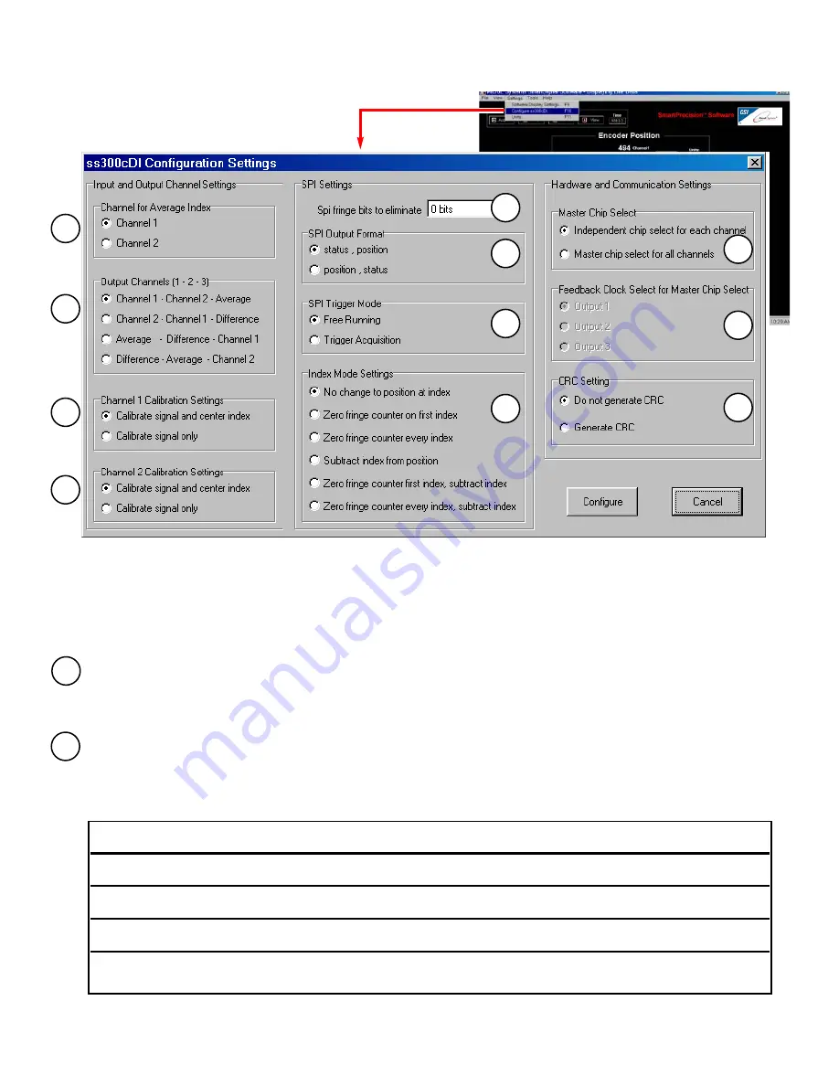
Selects the input channel index that will be used for the Averaged output.
Example shown: 

Index for Channel 1 selected

O

Ou

uttp

pu

utt  C

Ch

ha

an

nn

ne

ellss  [[11  --  22  --  33]]: 

The Mercury Dual Axis Averager uses two sensors as inputs and has three output channels. Each sensor's signal is processed for
accuracy enhancement and interpolated. The signals, or their average or difference, are routed to each of the three output channels.
The routing assignments can be changed using SmartPrecision Software in the Configuration Settings dialog box. There are four possi-
ble configurations for the output channel assignments as shown in the following table:

M3000SiDAA Configuration

Configurations screen

Output Configuration

Assignment for Output

Assignment for Output

Assignment for Output

Channel 1

Channel 2

Channel 3

"Channel 1 - Channel 2 - Average"

Sensor 1

Sensor 2

Average of Sensor 1

and Sensor 2

"Channel 2 - Channel 1 - Difference"

Sensor 2

Sensor 1

Difference 

(Sensor 1 minus Sensor 2)

"Average - Difference - Channel 1"

Average of Sensor 1 

Difference 

Sensor 1

and Sensor 2

(Sensor 1 minus Sensor 2)

"Difference - Average - Channel 2"

Difference 

Average of Sensor 1 

Sensor 2

(Sensor 1 minus Sensor 2)

and Sensor 2

1

2

1

2

3

4

5

6

7

8

9

10

11

Page  15

Содержание Dual Axis Averager Mercury 3000Si

Страница 1: ...ee ed db ba ac ck k U Us si in ng g A Av ve er ra ag gi in ng g o of f T Tw wo o S Se en ns so or rs s I In ns st ta al ll la at ti io on n M Ma an nu ua al l a an nd d R Re ef fe er re en nc ce e G...

Страница 2: ...This product is sold solely for use as a component or replacement in an electronic product therefore it is not required to and does not comply with 21 CFR 1040 10 and 1040 11 which pertain to complete...

Страница 3: ...ation Rotary 7 REFERENCE SECTION Installation of Linear Scales 8 Grounding Instructions 9 Recommendations for Power 9 Customer Interface Cable Requirements 10 Serial Output Specifications 11 12 SMARTP...

Страница 4: ...A 25 pin High Density D sub connector Signal Sensor 1 S Sy ys st te em m V Vi ie ew w Shown with linear scale Glass scale shown mounted on a linear slide Sensors shown attached on a linear slide base...

Страница 5: ...ecision electronics module interpolator E Ex xp pa an nd de ed d V Vi ie ew w Rotary scale Mounting hole 2 Top reflective rotary scale Typical user supplied sensor mounting bracket Mounting screws fla...

Страница 6: ...er is off before connecting the SmartPrecision plug Connect the SmartPrecision electronics to the controller using the pinout diagram described on the interface drawing Insure proper system grounding...

Страница 7: ...UR RE E This procedure must be completed for proper system operation each time the sensors are aligned or if the SmartPrecision electronics module is replaced Position each sensor at least 7mm 1 4 awa...

Страница 8: ...roller using the pinout diagram described on the interface drawing Insure proper system grounding Refer to the procedure on pg 9 Power up the system The Power and Signal indicators for both sensors wi...

Страница 9: ...ystem operation each time the sensors are aligned or if the SmartPrecision electronics module is replaced Position each sensor at least 7mm 1 4 away from the index mark on the scale Next for sensor 1...

Страница 10: ...face is clean and dry Optionally scale clamps may be used to secure the scale while the adhesive cures Avoid damage to the top surface Side view showing optional scale clamps and scale Space clamps ev...

Страница 11: ...e encoder connec tors in the diagrams below Note For best performance isolate encoder shield from motor cable shields and separate encoder cable as far possible from motor cables Sensors mounted to a...

Страница 12: ...ng twisted pair as follows Shield Termination The customer s cable shield should be in 360 contact with the connector shroud and the connector shell to provide complete shielding The connector shell s...

Страница 13: ...0Si Dual Axis Averager Interpolator has the ability to output a position word in a serialized format This allows very fast communication between an interpolator and customer application The speed limi...

Страница 14: ...oximately one fringe wide By monitoring the edges of the window with respect to the absolute sub fringe position during the index capture mode an accurate index position is calculated and stored At po...

Страница 15: ...elect Search for a suitable driver for my device recommended and press the Next button 4 Select Specify a location under Optional search locations and press the Next button 5 Press the Browse button t...

Страница 16: ...ch output can be reset or zeroed independently The units can be changed from encoder counts to any number of linear or rotary units S Se et tu up p Calibrate Starts the calibration routine for the sel...

Страница 17: ...artPrecision Software in the Configuration Settings dialog box There are four possi ble configurations for the output channel assignments as shown in the following table M3000SiDAA Configuration Confi...

Страница 18: ...igure how the serial word data is manipulated when encountering the index angle position M Ma as st te er r C Ch hi ip p S Se el le ec ct t Allows one hardware Chip Select to be used for all channels...

Страница 19: ...shot of the interpolator con figuration as well as Index posi tion indication The indicator light on the SmartPrecision soft ware mimics the LED on the M3000SiDAA The indicator will be green as long a...

Страница 20: ...indication for Channel 1 will rapidly blink until the calibration routine is complete To calibrate Channel 2 Through Software Select CALIBRATE SIGNAL on INPUT CHANNEL 1 Through Hardware Push the reces...

Страница 21: ...ing The number of data points to be plotted on the graph at one time can be changed using the Plot Settings button The processed Green and or the pre processed Red signals can be shown on the graph Pl...

Страница 22: ...ut 2 8 Serial Data Output 2 9 Chip Select Input 2 10 Chip Select Input 2 11 Serial Clock Input 2 12 Serial Clock Input 2 13 Serial Data Output 3 14 Serial Data Output 3 15 Chip Select Input 3 16 Chip...

Страница 23: ...al Data Output Output 5 SDO Serial Data Output Output 4 spiClockOut SCF Serial Clock Feedback Output 10 SCF Serial Clock Feedback Output 9 Operational Modes Standard Communication Mode The falling edg...

Страница 24: ...me 50 ns tCSC n_spiEnable to spiClock 0 ns tCSD n_spiEnable to DataValid 80 ns tV spiClock to Data Valid 80 ns tCCS spiClock to n_spiEnable 0 ns tCS n_spiEnable High 50 ns All timing are specified ass...

Страница 25: ...Software In this mode triggering is controlled by the n_spiEnable signal The falling edge of n_spiEnable signal starts the process by immediately resetting the internal calculators and acquiring the...

Страница 26: ...n other than the intended direction Make sure that each scale is clean over its entire length or circumference Problem The green Power Calibration indicator is flashing unexpectedly Solution Part of t...

Страница 27: ...the edges Do not scrub the scale World Headquarters 125 Middlesex Turnpike Bedford MA 01730 USA www microesys com info microesys com T 781 266 5700 F 781 266 5112 2008 MicroE Systems Thank you for pu...

Отзывы: