UCS81003 EVALUATION
BOARD USER’S GUIDE
2014 Microchip Technology Inc.
DS50002300A-page 13
Chapter 2. Installation and Operation
2.1
INTRODUCTION
This chapter identifies the main connectors, LEDs, jumpers and test points that can be
found on the UCS81003 Evaluation Board. It also explains the steps to install the
board’s graphical user interface.
2.2
CONNECTORS ON THE EVALUATION BOARD
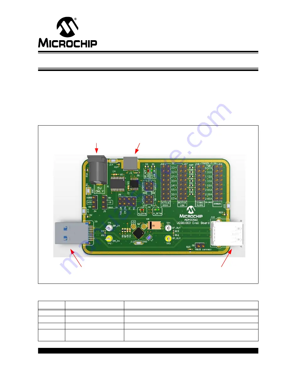
shows the top of the evaluation board and highlights the connectors.
FIGURE 2-1:
UCS81003 Evaluation Board Top View – Connectors.
TABLE 2-1:
CONNECTOR DESCRIPTIONS
Designator
Connector Type
Description
J1
Power jack
External 5V power supply
J2
USB Mini-B receptacle
This connects the board to the PC with the GUI software
J3
USB Standard-A plug
This connects the evaluation board to the USB host
J10
Right-Angle USB Standard-A
receptacle
This connects the board to the portable device
J2
USB Mini-B
receptacle
to PC
J10
USB Standard-A receptacle
to portable device
J3
USB Stanadrd-A plug to
USB host / USB Power
J1
Auxiliary power connector
to external power supply
Содержание UCS81003
Страница 1: ... 2014 Microchip Technology Inc DS50002300A UCS81003 Evaluation Board User s Guide ...
Страница 4: ...UCS81003 Evaluation Board User s Guide DS50002300A page 4 2014 Microchip Technology Inc NOTES ...
Страница 10: ...UCS81003 Evaluation Board User s Guide DS50002300A page 10 2014 Microchip Technology Inc NOTES ...
Страница 42: ...UCS81003 Evaluation Board User s Guide DS50002300A page 42 2014 Microchip Technology Inc NOTES ...
Страница 51: ...Bill of Materials 2014 Microchip Technology Inc DS50002300A page 51 NOTES ...


