


UCS1003-1
EVALUATION BOARD
USER’S GUIDE
2016 Microchip Technology Inc.
DS50002510A-page 25
Chapter 4. Software Description
4.1
OVERVIEW
To get the graphical interface and the evaluation board running, follow these
instructions:
1. Start the UCS81003/UCS1003-1 GUI software: from the Windows Start menu,
select
Programs > Microchip > UCS81003
.
2. Connect the USB mini connector end of the cable to the board and the standard
USB connector of the cable to any available USB port on the PC. If the V
DD
supply is connected to V
S
(the jumper on J4 header is populated on position 2-3),
then connect the V
S
supply. The USB Activity LED should light, indicating that
the MCP2221 USB bridge is connected to the PC.
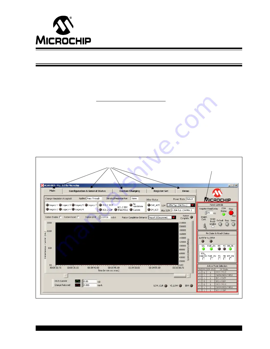
The UCS81003/UCS1003-1 Evaluation Board interface (
), consists of five
tabs (
Main
,
Configuration & General Status
,
Custom Charging
,
Register Set
and
Demo
) and the right-side sections that are always visible (
Panel Controls
,
Pin State
& Attach Status
and
Active Mode Selection
).
FIGURE 4-1:
UCS81003/UCS1003-1 Evaluation Board GUI Initial Window.
Tabs
Fixed panel
with controls
Содержание UCS1003-1
Страница 1: ...2016 Microchip Technology Inc DS50002510A UCS1003 1 Evaluation Board User s Guide...
Страница 3: ...2016 Microchip Technology Inc DS50002510A page 3 Object of Declaration UCS1003 1 Evaluation Board...
Страница 4: ...DS50002510A page 4 2016 Microchip Technology Inc NOTES...
Страница 6: ...UCS1003 1 Evaluation Board User s Guide DS50002510A page 6 2016 Microchip Technology Inc NOTES...
Страница 10: ...UCS1003 1 Evaluation Board User s Guide DS50002510A page 10 2016 Microchip Technology Inc NOTES...
Страница 22: ...UCS1003 1 Evaluation Board User s Guide DS50002510A page 22 2016 Microchip Technology Inc NOTES...
Страница 48: ...UCS1003 1 Evaluation Board User s Guide DS50002510A page 48 2016 Microchip Technology Inc NOTES...


