UCS1003-1 Evaluation Board User’s Guide
DS50002510A-page 30
2016 Microchip Technology Inc.
4.2.4
Active Mode Selection
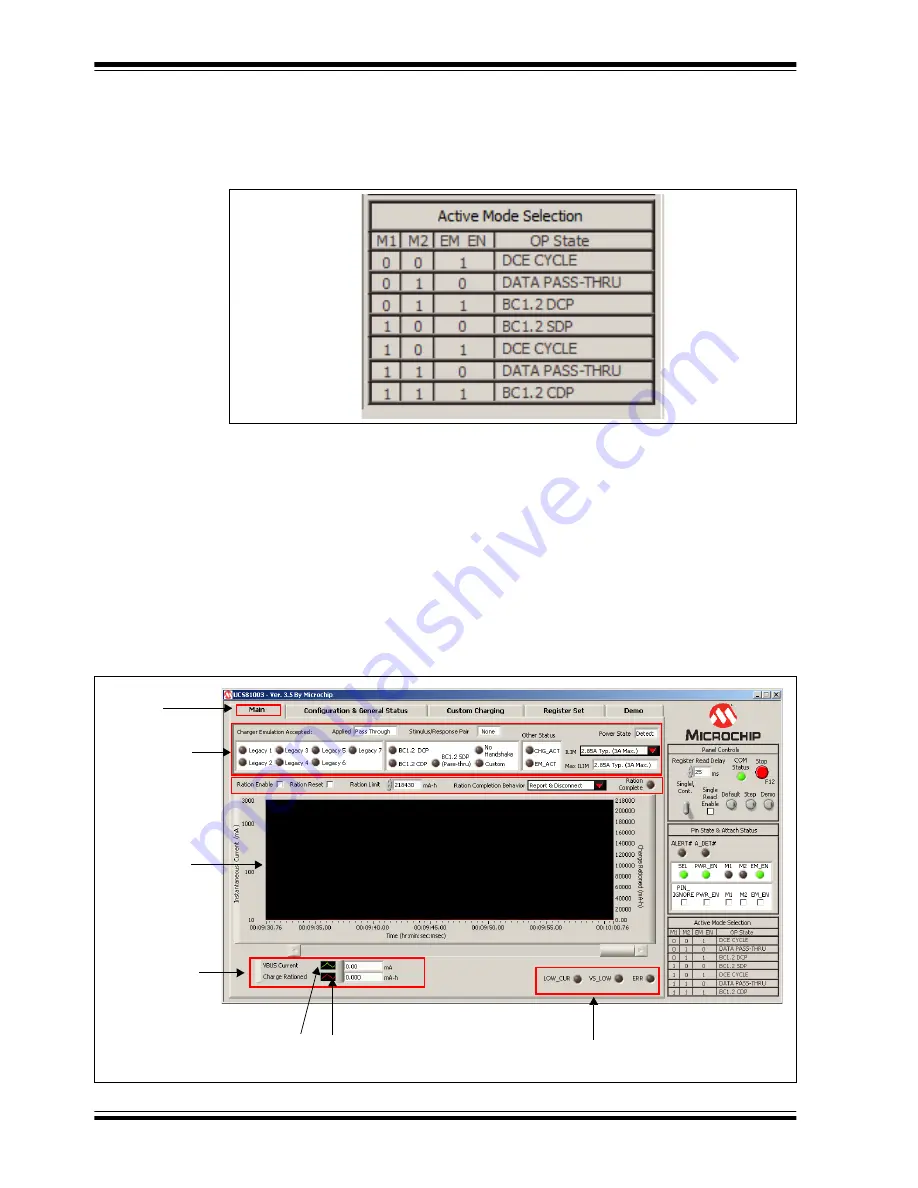
The Active Mode Selection section on the right side of the GUI, shown in
provides a quick reference regarding operating state based on the values of M1, M2
and EM_EN. This section is always displayed.
FIGURE 4-5:
Charger Emulation Selection.
4.3
TAB DESCRIPTIONS
4.3.1
Main Tab
The
Main
tab (
) shows key parameters related to the port power switch,
including the maximum current limit, the present current limit (always equal to or less
than the maximum current limit), and power state (e.g. detect, active, error, etc.). When
a portable device has been successfully attached, the screen shows the power state
change from Detect to Active and shows the various handshakes applied. Once it is
determined that the device is charging, the screen shows which emulation profile was
successful, and the graph shows the charging current. Optionally, the user may monitor
the charge delivered or ration the charge delivered to the attached device.
FIGURE 4-6:
Main Tab Window Overview.
Tab
Status panel
Measured
current
status
Right-click wave box
for plot appearance settings
Current status
Instantaneous
current
measurement
screen
selection
Содержание UCS1003-1
Страница 1: ...2016 Microchip Technology Inc DS50002510A UCS1003 1 Evaluation Board User s Guide...
Страница 3: ...2016 Microchip Technology Inc DS50002510A page 3 Object of Declaration UCS1003 1 Evaluation Board...
Страница 4: ...DS50002510A page 4 2016 Microchip Technology Inc NOTES...
Страница 6: ...UCS1003 1 Evaluation Board User s Guide DS50002510A page 6 2016 Microchip Technology Inc NOTES...
Страница 10: ...UCS1003 1 Evaluation Board User s Guide DS50002510A page 10 2016 Microchip Technology Inc NOTES...
Страница 22: ...UCS1003 1 Evaluation Board User s Guide DS50002510A page 22 2016 Microchip Technology Inc NOTES...
Страница 48: ...UCS1003 1 Evaluation Board User s Guide DS50002510A page 48 2016 Microchip Technology Inc NOTES...


