background image

QUICK HOSE REWIND

The purpose of the PTO shaft on the gearbox is to rewind the hose quickly by using the tractor.  If for any
reason you need to wind the hose up quickly then follow these steps.
1.  

WARNING! 

 Make sure the handle on the gearbox is in the idle or disengaged position, otherwise

      severe damage will occur to the gearbox.  Disengage the anti-reverse lever.
2.   Connect the tractor PTO drive line to the gearbox shaft on the Micro Rain.  

WARNING!  

Read

      drive-line directions for proper use of the PTO drive-line.  Neither Micro Rain nor Micro Rain
      dealers are responsible for improper use of the drive line which can result in injury or death.
3.   Slowly activate the tractor power take off and the reel will begin to wind up. Roll up hose at the slowest
      possible RPM.


IMPORTANT!!

  Do not engage PTO with high RPM.  This can damage the drive gear.


    IMPORTANT!!  

When using the PTO shaft, there is no automatic stop at the end of the run.

The PTO must therefore be stopped before the hose is completely wound up to avoid damage to the gun
cart or the end of the hose.  It is recommended the final wrap or two to be wound up manually.


    IMPORTANT!!  

To avoid irregular rewinding of the hose when using a PTO, it may be neces-

sary to wind the hose up under water pressure to avoid excessive ovaling of the hose.

MAINTENANCE

1.   Grease all grease fittings every 100 hours of operation.
2.   Grease all wheel hubs every 100 hours of operation.
3.   Grease the drum gear at least twice per season.
4.   Change the gearbox oil every season.
5.   Check tire pressure every 4-6 weeks.

WINTERIZING

1.   Remove plug or open petcock placed under the turbine ( fig 1 ).
2.   Remove drain plug on bottom of gun cart.
3.   If the machine is equipped with the blue diaphram valve (machines prior to 2002 model), the black filter
      body (fig 2), and blue valve must be drained (fig 3).
4.   If the machine has a boost pump, then the pump volute and plumbing must be drained.
5.   Machines equipped with the cart shut-off valves (2002 - present machines) must leave valve in the open
      position to avoid freeze damage.  Note:  Open and close valve several times before leaving valve open.

14

FIG 1

       FIG 2

FIG 3

Содержание MR40

Страница 1: ...MICRO RAIN INSTRUCTION MANUAL FOR OPERATION AND MAINTENANCE MR40 MR43 ...

Страница 2: ...gs When the traveler is equipped with shut off valve the supply hose remains pressurized at the end of the run First relieve the pressure then disconnect the supply hose Use caution with the sprinkler heads Guns Pressurized water from the sprinkler head could cause serious damage to people or objects Use caution during transport Travelers are not made for public transit Do not exceed 7mph on flat ...

Страница 3: ...ight and Dimensions 7 Transport and Assembly 8 9 Start Up Maintenance Procedures 10 12 Standard Hose Rewind 13 Quick Hose Rewind Maintenance Winterization 14 Care and Repair of P E Tube 15 16 Troubleshooting 17 Warnings 18 Use of Shut Off Valves 19 Booster Pump 20 25 Performance Charts 26 27 ...

Страница 4: ...ot release the clamps before making sure that the pressure is released 3 This sign indicates dangerous equipment in operation Never use this machine with safety guards removed When using a PTO to rewind the hose use only protected shafts conforming with the safety standards in force 4 This sign indicates a risk of electric power danger Never position the sprinkler cart close to power supplies Make...

Страница 5: ...e machine read the instruction manual carefully 6 Before servicing or making any adjustments stop the machine and disconnect the supply line 7 Do not stand between the hose reel and gun cart while machine is in operation 4 ...

Страница 6: ...tdesignedfordirtywaterorslurry wastewaterconditions IDENTIFICATION DATA The KID ID Plate includes a model number ie MR 43 MR 58BP and a serial number The ID plate is located on the left side of the machine cover side on the frame plate just above the rear tire 5 SPECIAL LABELS ON SPRINKLER CART VALVE CAUTION GEARBOXWARNING ...

Страница 7: ...rbox engage and disengage 4 Shut off valve handle 2 Anti reverse handle 5 Speed is regulated by adjusting the by pass 3 Automaticdisengagebar 6 Electric motor regulates by pass when using the optional GOLDEN RAIN computer 6 ...

Страница 8: ...ions of the machine use lift winches and equipment with dimensions and capacities proportioned to the weight of the machine to be lifted see tables 7 DIMENSIONS INCHES A B C D MR 40 76 59 50 50 MR 43 76 59 50 50 WEIGHT LBS DRY WITHWATER MR40 538 783 MR43 559 806 ...

Страница 9: ...AIN DEALERS ARE RESPONSIBLE FOR ANY INJURY OR MACHINE FAILURE DUE TO LACK OF PROPER SAFETY PROCEDURES OR FAILURE TO READ AND FOLLOW INSTRUCTIONS 8 1 Micro Rain travelers are either shipped on a special skid partially disassembled which can be un loadedwithaforklift or theyareshippedinafullyassembledstatebyblockingontheshippingfloor 2 The proper procedure to unload the skid shipment is with a fork ...

Страница 10: ...un Cart fig 1 a Push the end of the P E hose onto the guncart as indicated in fig 3 Applying heat to the end of the P E hose will ease this process b Tighten the clamp provided with the bolts on top c Mount the sprinkler gun onto the gun cart Use teflon tape or a thread compound to provide a proper seal d Using the hand grip pick up the gun cart and hook it onto machine fig 2 FIG 1 FIG 2 9 ...

Страница 11: ...n the drum inlet One grease fitting is located on the bottom side and lubricates the drum inlet seals Grease must be spread on the drum gear teeth and at the drive shaft where the drum gear and drive gear mesh The scroll bar must also be kept well greased and the scroll knife must be lubricated grease fitting in order to function correctly 3 Check the tire pressure and if necessary inflate to pres...

Страница 12: ...s straight as possible FIG 1 3 Set the stabilizer fig 1 4 Lower the gun cart 5 Connect the water supply hose to the water inlet connection on the machine fig 2 NOTE Before connecting the supply hose to the machine flush out hose or check to be sure there is no foreign matter which will block the turbine FIG 2 6 Release the backstop anti reverse lever fig 3 Pull straight back and down to release 7 ...

Страница 13: ... Turn speed control in the clockwise direction to slow reel to the desired speed If computer speed control system see page 13 for specific instructions on operation 11 When you have pulled out the hose make sure that the wraps remaining on the reel are tight and close together next to the edge of the drum If necessary roll the drum by hand to tighten wraps and push them in place by hand fig 8 This...

Страница 14: ...gear allowing the gears to mesh This process is best completed with water running through the turbine 4 Adjust hose retraction speed On a manual speed control machine this is completed by adjusting the position of the bypass valve fig 3 Full reel speed is achieved with the valve turned full counter clockwise To slow the retraction speed slowly turn the bypass valve clockwise until the desired retr...

Страница 15: ...d before the hose is completely wound up to avoid damage to the gun cart or the end of the hose It is recommended the final wrap or two to be wound up manually IMPORTANT To avoid irregular rewinding of the hose when using a PTO it may be neces sary to wind the hose up under water pressure to avoid excessive ovaling of the hose MAINTENANCE 1 Grease all grease fittings every 100 hours of operation 2...

Страница 16: ...ne with the anti reverse lever engaged and cart racked 3 Do not attempt to operate the machine with loose or misplaced wraps of tube Tighten the tube on the drum before starting the machine WARNING Starting the machine without tightening the tube wraps will result in miswrapping and could permanently damage your tube 4 Do not attempt to move or relocate the machine with tube unwound All the tube m...

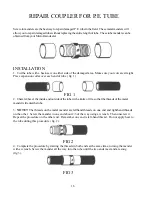
Страница 17: ...el the inside and outside of the tube with a knife or file so that the threads of the metal menderwillenterthetube 3 NOTE The threads on the metal mender are lefthand threads on one end and righthand threads on the other Screw the mender in one end about 2 3 of the way using a wrench Then unscrew it Repeat the procedure on the other end Remember one end is left hand thread Do not apply heat to the...

Страница 18: ... wood under in order to reduce friction RECOMMENDATIONS When moving the machine never exceed the maximum speed of 7 MPH If the hose is wound up using the PTO be certain the gearbox is in the idle or disengaged position or the gearbox will be seriously damaged At the beginning of each season completely unwind the hose leaving only two wraps on the reel ANYMODIFICATION MADE TOANYPART OFTHE MACHINE W...

Страница 19: ...n use Thisappliesespeciallytounauthorizedpeople When the machine is being transported on a grade of 6 degrees or greater there is a risk of the machine overturning Take every precaution to avoid transporting on steep grades Make sure that in the rain gun sprinkler head path of irrigation there are no electrical wires or power lines Tremendous water pressure comes through the hose to the gun Avoid ...

Страница 20: ...lling the cart out for the next irrigation run shift the gearbox back into neutral The gearbox will be seriously damaged if the hose is unwound with the gearbox still engaged FIG 1 FIG 2 OPTIONAL DIAPHRAM VALVE SHUT OFF 19 1 Thediaphramvalve Fig3 isactuatedbytherollerswitch bulletmechanism Fig4 Forirrigation operation the bullet must be completely off of the roller switch 3 way valve 2 Whenthecart...

Страница 21: ...as in structed by the engine manufacturer to avoid pump or machine damage Micro Rain or Micro Rain Dealers are not responsible nor liable for operator failure to follow engine and machine instruc tions and guidelines Remove the gas cap and fill the gas tank to the side of the engine with gasoline and replace the cap Do not over tighten gas cap Check gas level often to be sure engine has fuel fig 1...

Страница 22: ... hose to the quick connect fitting fig 3 on the machine FIG 3 2 If your machine has a shut off valve fig 4 make sure the valve handle is in the working up position FIG 4 3 Turn on the water source and pressure to the machine 21 ...

Страница 23: ... through the machine 4 Turn on the gas switch as indicated in fig 5 FIG 5 5 If the engine is cold choke the engine by pushing the switch to the left fig 6 FIG 6 6 Start the engine by pulling on starter rope Fig 7 or by turning ignition key clockwise Fig 8 FIG 7 FIG 8 22 ...

Страница 24: ...tivates the shut off valve When the valve is closed the flow switch mounted on the cross pipe fig 8 sensesthelossofwaterflowandautomaticallykillstheengine FIG 8 FIG 9 23 Note Water should always be running through the pump prior to starting boost pump but if for some reason the pump must be started without water flow for short duration the by pass button can be pressed to over ride the flow switch...

Страница 25: ...turned off and cooled down FIRE EMERGENCY 1 In case of fire use a powder fire extinguisher BATTERYINSTRUCTIONSAND USE 1 Theelectrolyteisadilutedsulfuricacidsolution Incaseofcontactwithskin washimmediately Contact medical help immediately if solution gets in your eyes WARNING When recharging any battery a flammable gas is produced which could cause battery to explode 2 Avoid sparks when attaching o...

Страница 26: ... BOOSTER PUMP THE ENGINE DOES NOT START The machine does not have water pressure The flow safety switch will not allow the engine to start with waterrunningthroughthemachine Aclosed shut off valve Solution Make sure the handle is in the up position open for operation Fig1 Flowswitchismalfunctioning Solution Remove switch and check contacts and wiring Replace if necessary Fig 2 FIG 1 FIG 2 Check oi...

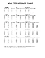
Страница 27: ...79 11 57 17 36 85 21 1 134 107 494 2 25 5 61 11 23 16 84 95 22 8 139 111 497 2 16 5 39 10 78 16 17 9 mm Nozzle 80 RUN TIME HRS INLET PSI GPM MAXWIDTH ADJ WIDTH MAXLENGTH 0 10 INCH 0 25 INCH 0 50 INCH 0 75 INCH 55 19 112 90 483 2 08 5 21 10 42 15 63 65 21 5 118 94 486 1 94 4 85 9 70 14 56 75 23 128 102 491 1 97 4 92 9 84 14 76 85 24 8 134 107 494 1 91 4 78 9 55 14 33 95 26 8 139 111 497 1 83 4 59 9...

Страница 28: ...5 65 23 128 102 457 1 81 4 53 9 06 13 58 75 24 2 134 107 460 1 80 4 51 9 01 13 52 85 26 5 139 111 463 1 71 4 27 8 54 12 80 95 28 7 146 117 466 1 80 4 14 8 28 12 42 10 mm Nozzle 80 RUN TIME HRS INLET PSI GPM MAXWIDTH ADJ WIDTH MAXLENGTH 0 25 INCH 0 50 INCH 0 75 INCH 1 00INCH 55 24 3 120 96 453 4 02 8 04 12 05 16 07 65 26 130 104 458 4 07 8 14 12 20 16 27 75 29 7 140 112 463 3 84 7 67 11 51 15 34 85...

Страница 29: ...28 ...

Отзывы: