


Page 9
scanCONTROL 25xx
- RS422 interface
Modbus RTU protocol
Transmission of measurement values in ASCII format
11.
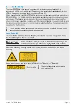
2D/3D Gateway
2D/3D Gateway allows for scanCONTROL SMART sensors to be integrated into various
fieldbus systems:
- PROFINET
- EtherNet/IP
- EtherCAT
All measurement results obtained from the profile evaluation performed by a
scanCONTROL SMART sensor can be transmitted to a PLC via one of these fieldbus
systems. Furthermore, all scanCONTROL sensor settings can be set via the 2D/3D
Gateway (e. g. Laser on/off or User Mode).
Sensor
parameterization
Supply voltage
Triggering
Encoder
Synchronization
Mode switching
Sensor control
Gateway parameterization
USB
Ethernet
switch
2D/3D Gateway
The 2D/3D Gateway can connect up to four scanCONTROL SMART sensors to the
fieldbus. Measurement values are transmitted at up to 500 Hz.
Please refer to the TechNote T026 (scanCONTROL fieldbus integration) for more de-
tails.