


Page 3
scanCONTROL 25xx
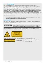
Laser Class 3B
The sensors with the /3B option fall within laser class 3B. The laser is operated on a
pulsed mode, the maximum optical power is
≤ 50 mW.
Laser radiation. Wear suitable protective glasses. Injury of the
eyes and the skin are possible.
Attach the following warning labels to the cover (front and rear side) of the sensor
housing:
IEC 60825-1: 2014
P
≤
50mW, P
≤
50mW;
0
P
= 658nm; F = 0...4kHz, t = 1µs...
∞
WARNING - LASER RADIATION
AVOID EXPOSURE TO BEAM
CLASS 3B LASER PRODUCT
In addition, the following information la-
bel must be attached to the laser output
on the sensor housing:
LASER
APERTURE
Laser warning sign and laser label, LLT25xx-25, LLT25xx-50, LLT25xx-100
COMPLIES WITH 21 CFR 1040.10 AND 1040.11
EXCEPT FOR CONFORMANCE WITH
IEC 60825-1 ED. 3., AS DESCRIBED IN
LASER NOTICE NO. 56, DATED MAY 8, 2019
Only for USA
Class 3B laser sensors are notifiable and a laser protection officer is required.
Mark the laser area recognizable and everlasting. During operation the laser area has
to be restricted and marked.
i
Sensors of laser class 3B requiry an external key switch to switch off the laser, see
operating instructions Chap. 5.2.6.
Beam attenuator
Laser products certified as Class 3B products (EN 60825-1) require a beam attenuator,
other then the key-operated control. The beam attenuator prevents access to all laser
and collateral radiation.
Sensor with close beam
attenuator
Sensor with open beam atte-
nuator for measurements
To open or close the aperture please follow the steps below:
Loosen the knurled screw
Change the attenuator position and tighten the knurled screw.
The laser aperture must be open during measurement. Please observe the notes on
external laser switching, see operaring instructions Chap. 5.2.6.