


Page 6
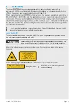
scanCONTROL 25xx
If the sensor is connected to a POE-capable network adapter/
switch and you also use the power supply of the multifunction
port, these two power supplies must be galvanically isolated.
> Damage to the sensor and/or Ethernet card!
- A fixed IP address can be assigned.
Use the
sensorTOOL
program to specify the sensor settings
described above.
The program is available online at
www.micro-epsilon.com/download/software/sensor-
LED Indication
LED
laser on
Meaning
laser on
state
Green
Laser is on
LED
state
Meaning
Green
Measurement is active
Green, flashes long
Data transmission is active
Green, flashes short
Controller is accessing laser
Red, flashes
Error code
6.
System Requirements
scanCONTROL Configuration Tools
The following minimum system requirements are necessary:
- Windows 7, Windows 8 or 8.1, Windows 10 (each 32 bit and 64 bit)
- 1 GHz processor or faster (32 bit and 64 bit) / 1 GB RAM (recommended 4 - 8 GB)
- Screen resolution: 1024 x 768 (recommended 1920 x 1080)
scanCONTROL 3D-View
The following minimum system requirements are necessary:
- Windows 8 or 8.1, Windows 10 (each 64 bit)
- 1 GHz processor or faster (64 bit)
- 1 GB RAM (recommended 16 GB)
- Screen resolution: 1024 x 768 (recommended 1920 x 1080)
- Graphics card / GPU with OpenGL 3.1 or higher