Initial Setup:
The antenna should be mounted at least 6 feet above ground for
the initial tune-up (higher if practical). If available, use a handheld antenna
analyzer -- it will make tuning a lot faster and safer. Also, when checking SWR,
back away from the elements -- especially in the area surrounding the end
insulators. If you get too close, you could detune them with your body. When
using a transmitter and SWR bridge to check SWR, apply the minimum amount
of power needed to calibrate the bridge and
do not make physical contact with
energized elements!
Tuning Procedure:
The element wires are pre-cut to resonate at or slightly
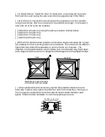
above the high-frequency edge of each band. The trim-tab tuning strips are
installed on the insulators to move the minimum-SWR frequency down toward
your favorite band segments without disrupting wire tensioning on the frame. To
lower frequency, position the tabs to electrically extend the element length. Start
with the 20-meter element and work your way in toward the 10-meter element.
Highest in Frequency
Lowest in Frequency
Middle Range
If minimum SWR occurs where you want to it without installing tabs, omit them. If
the tabs fail to pull the frequency low enough, swing one tab down so the end
hole is clear of the insulator and add a short length of wire using a 6-32 screw.
Bandwidth:
The 2:1 bandwidth for a half-wave loop is normally much narrower
than it is for a straight-line half-wave dipole, so tune carefully. Also, when
adjusting the antenna close to ground, you may fail to get a deep SWR dip on
one or more of the bands. In this event, tune for the best dip you can get at your
target frequency. The minimum SWR will drop substantially once the antenna is
repositioned at a higher location. After you've installed the antenna at its final
location, always double-check to ensure the lowest SWR points remain where
you want them. New surroundings may cause one or more points to shift. Take
the time to re-adjust -- it’s time well invested.
Antenna Tuners:
You may use the MFJ-1835 in conjunction with a tuner to
achieve full-band low-SWR coverage on the wider bands (20, 15, and 10
meters). A tuner will also prove helpful if the elements accumulate ice, snow, or
heavy rain (precipitation loading normally lower resonant frequency). However,
don't use your tuner to compensate for mistuned elements! Perform a careful
tune-up under dry conditions at the time of installation to ensure the best overall
performance.
Antenna Mounting:
The MFJ-1835 performs best when raised 20-feet or more
above ground and positioned well away from nearby wiring, metal surfaces, and
large conductive objects. Use any mast diameter between 1-1/4" and 1-3/4" OD,

