26
CHAPTER 7
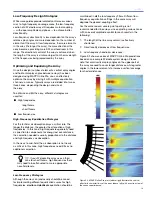
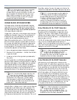
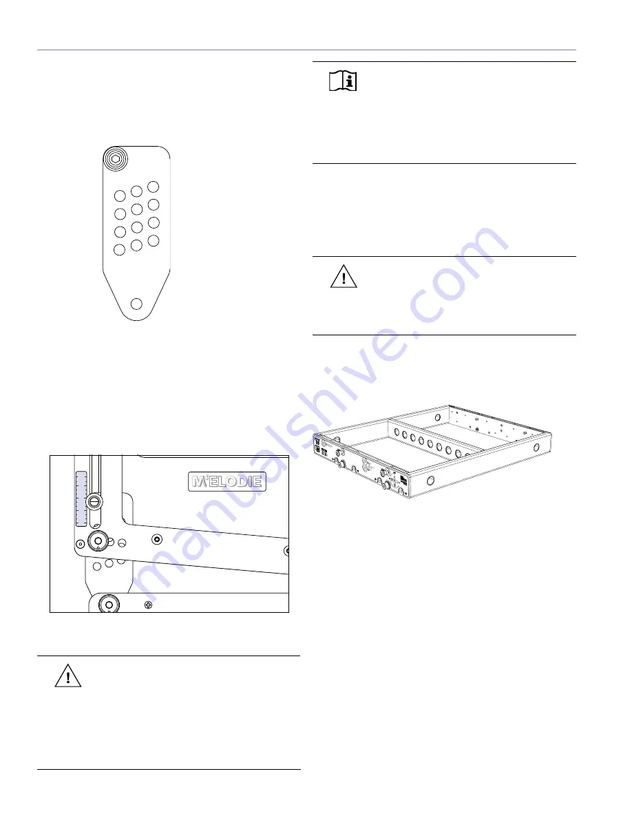
The rear GuideALinks permit 12 splay angles between 0 and
11 degrees in 1-degree increments. The GuideALink has
four rows each with 3 columns. The splay angle between
cabinets increases by one degree as the GuideAlink is
pinned in adjacent positions from front to back and top to
bottom.
��
��
��
��
���
��
��
��
��
��
��
���
Figure 7.3.
M’elodie GuideALink (shown removed from frame)
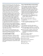
A small label on the end frame serves as a guide to pin
positions in the GuideALink, to help locate the find the
desired angle as the knob moves up the frame. In the
bottom position, the splay angle between cabinets is
0 degrees. As you move the knob upwards, the angle
increases to 11 degrees. To stow the link, the knob is
moved all the way up in the slot.
�
�
�
�
��
Figure 7.4. Use the
frame label as a guide when setting angles
CAUTION:
As part of the regular inspection
and maintenance procedure for M’elodie
loudspeakers, check each captive GuideALink
knob pin to ensure they are tight by turning them
counterclockwise by hand. If a pin turns, it must
be reset into the link using Loctite
®
290, and be
allowed to cure for 48 hours and retested before the
loudspeaker is flown.
NOTE:
Optimal acoustical performance for
a M’elodie array is achieved by using the
adequate number of units as well as selecting
the specific angles between cabinets to fill the
requirements of a venue. Use the design guidelines
in Chapter 5 to design systems and MAPP Online
Pro to verify designs and get rigging information.
THE MG-M’ELODIE MULTIPURPOSE GRID
The MG-M’elodie multipurpose grid allows multiple
M’elodie curvilinear array loudspeakers to be flown or
ground-stacked in numerous configurations.
CAUTION:
For complete information on load
ratings and how to set up the MG-M’elodie
and other M’elodie rigging accessories, please use
the MG-M’elodie Assembly Guide (part number
05.152.034.01) available on www.meyersound.com.
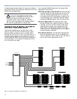
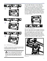
The MG-M’elodie grid can accommodate a variety of
pickup configurations using its four side pick-up points
and/or the nine center pick-up points.
Figure 7.5.
MG-M’elodie multipurpose grid is used to fly a M’elodie
array
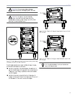
The MG-M’elodie grid can be rotated to allow you to fly
M’elodie loudspeakers in two positions with respect to the
grid. The “rear flown” position (M’elodie is closer to the rear
of the grid) is most useful for achieving superior uptilt in the
grid and the “front flown” position (M’elodie is closer to the
front of the grid) helps achieving more downtilt.
The MG-M’elodie has four captive grid links, each grid
link has 3 positions. In flown configurations, the first
M’elodie loudspeaker in the array can be connected to the
MG-M’elodie grid at 0°, -5°, and -10° depending on the
combination of the grid links position. In addition, the grid
links can be stowed for transport.
Содержание M'elodie
Страница 8: ...2 INTRODUCTION ...
Страница 20: ...14 CHAPTER 3 ...
Страница 42: ...36 APPENDIX C ...
Страница 43: ......


