


plate should be started squarely on the trunnion and
evenly tapped with a plastic mallet. With new bearings
it may be necessary to tap and rotate the plate all the
way on. Lubrication is helpful. Once installed, without
cocking, the plate will be snug but can be smoothly
rotated with a mallet or block of wood.
5. Align the trunnion plates relative to the ball port
as shown in Figure 5. This will approximate proper
position when the ball and trunnion plate subassembly
is lowered into the body.
6. With the ball in the closed position as shown in Figure
5, lower the ball/trunnion plate subassembly partially
into the body. NOTE: This procedure is critical and
careful attention must be paid to points A and B of the
plates as shown in Figure 5. The outside diameter of
the trunnion plate must pilot in the body counter-bore.
Carefully lower the subassembly until a trunnion
plate enters the counter-bore. Usually one plate will
enter the counterbore and the other plate will be out
of position. When this happens it is due to the plates
not being in perfect alignment per step 5, or not being
parallel to each other. Use a plastic mallet or block of
wood to rotate the second trunnion plate and cause it
to drop into position. It might be necessary to lift the
ball slightly. Lower the subassembly until the trunnion
plates are seated in the bottom of the cavity.
7. Slide the stem bearing (8) over the top of the stem
(4) and down to the stem shoulder. Place a secondary
stem seal (7) over the stem and down on top of the
stem bearing (8).
8. Slide the stem retainer (30) over the stem and down on
top of the secondary stem seal (7).
9. Slide the upper stem seal set (32) over the stem and
down into the stem retainer. (“V” shape of stem seals
must point away from the ball (See Figure 5).
10. Slide the compression ring (21) over the stem and down
to the upper stem seal set (32) in the stem retainer.
11. Place the stem nut (15). with the side marked “top”
up over the stem and thread it down until contact is
made with the compression ring. (Use a wrench on the
bottom stem blade to keep the stem from turning.)
12. Tighten the stem nut until the stem seal set is fully seated,
then tighten the nut an additional 1/8 to 1/4 turn.
13. Place the stem retainer seal (25) in the bonnet groove
of the body (1).
14. Place the stem subassembly into the body bonnet hole
and engage the stem in the ball slot. The groove on top
of the stem should be parallel to the ball waterway.
15. Align the stem retainer flange holes with the tapped
holes in the body bonnet. Lubricate the hex head
cap screws (29) with Never-Seez or equivalent. Place
the four hex head cap screws (29) through the stem
retainer flange and thread into the body. Tighten with
sequence and torque per Table 4 and Figure 4. Install
the drive key (33) on the key drive stems.
16. Place the body seal (6) in the body groove. NOTE: The
ball must be in the closed position before proceeding
to step 17. Do not install the body cap (2) with the ball
in any other position.
17. Lower the body cap (2) with the seat onto the body. pay
careful attention to the alignment with the trunnion
plates as described in step 6. NOTE: Some valves have
an alignment pin (41) or have the bolt holes spaced so
that the body cap can only be installed one way.
18. Using Never-Seez or equivalent, lubricate the threads
and underside face of each body fastener. Tighten
with sequence and torque per Table 4 and Figure
4. REMOUNTING ACTUATOR When an actuator is
remounted on the valve it may be necessary to readjust
the actuator travel stops to ensure proper setting of
the ball in the open and closed position. Follow the
procedure in step 19 for proper adjustment.
19. Adjust the actuator stop adjusting screws for proper
ball position when in the full open and full closed
position. For proper alignment, follow these guidelines:
A. Valve Open Position: Allowable misalignment of
the ball port in relation to the body port should not
exceed 1/16”.
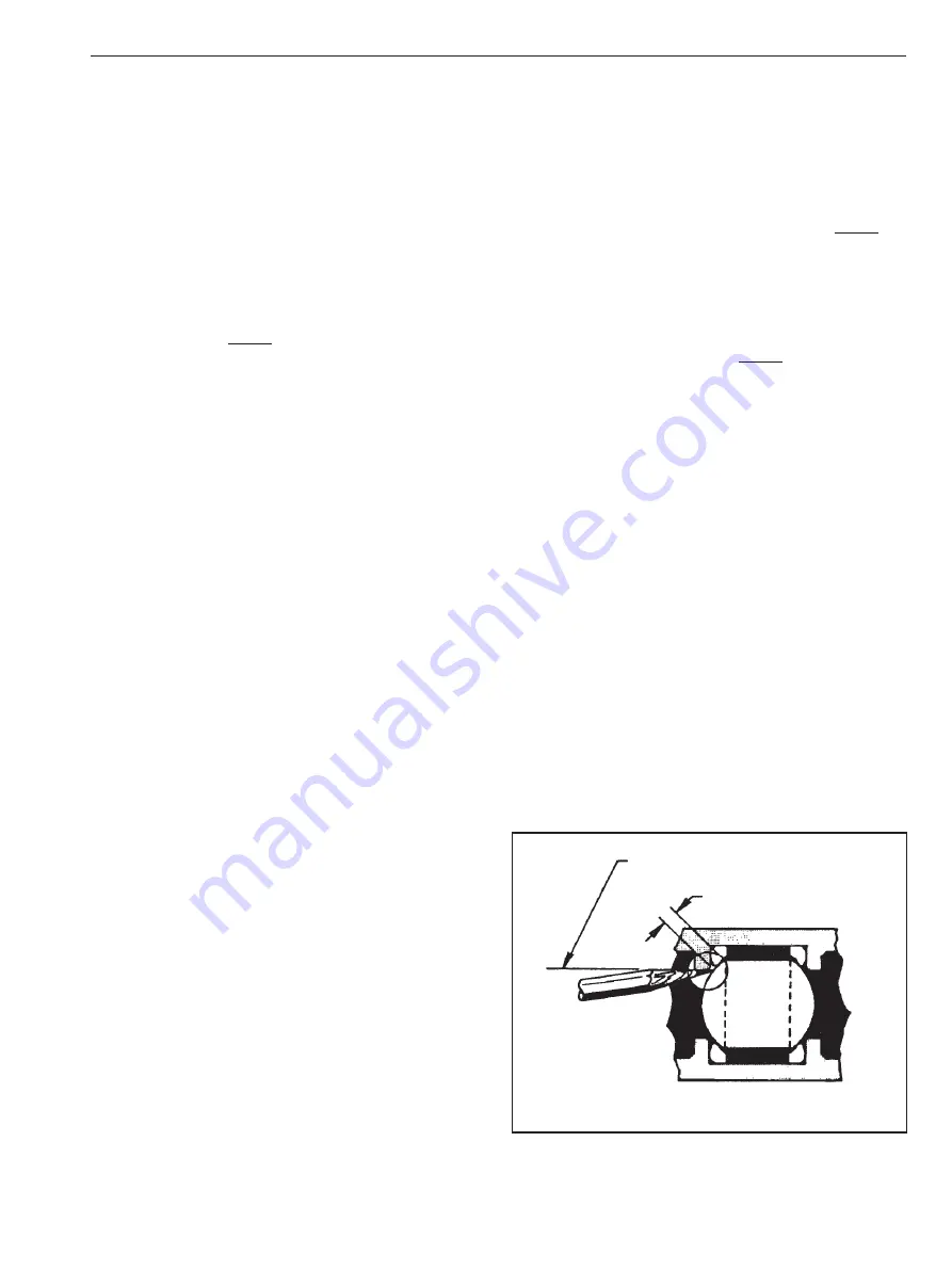
B. Valve Closed Position: Scribe a pencil mark on the
ball as shown in Figure 3. Open the valve and
measure dimension.
Figure 3
In line with Waterway
B
IMO 11/17
IMO-302 EN
5
Содержание 5300
Страница 11: ...IMO 11 17 IMO 302 EN 11 ...