


1.
GENERAL
1.1
Scope of the Manual
This instruction manual contains important information
regarding the installation, operation and maintenance of the
Jamesbury® Reactor Discharge Valves 8” - 12” 530S & 5300,
6” - 10” 6300 Digester Blow Valves, 8” -12” 530SB & 5300SB
and 6” - 10” 6300B Flanged Ball Valves. Please read these
instructions carefully and save them for future reference.
WARNING
FOR YOUR SAFETY, IT IS IMPORTANT THAT THE FOLLOWING
PRECAUTIONS BE TAKEN PRIOR TO REMOVAL OF THE VALVE FROM
THE LINE OR BEFORE ANY DISASSEMBLY:
1.
WEAR ANY PROTECTIVE CLOTHING OR EQUIPMENT NORMALLY
REQUIRED WHEN WORKING WITH THE FLUID INVOLVED.
2.
DEPRESSURIZE THE LINE AND CYCLE THE VALVE AS FOLLOWS:
A. PLACE THE VALVE IN THE OPEN POSITION AND DRAIN THE
LINE.
B. CYCLE THE VALVE TO RELIEVE RESIDUAL PRESSURE IN THE
BODY CAVITY BEFORE REMOVAL FROM THE LINE.
C. AFTER REMOVAL AND BEFORE ANY DISASSEMBLY, CYCLE
THE VALVE AGAIN SEVERAL TIMES.
3.
SEAT AND BODY RATINGS - THE PRACTICAL AND SAFE USE OF
THIS PRODUCT IS DETERMINED BY BOTH THE SEAT AND BODY
RATINGS. READ THE NAME TAG AND CHECK BOTH RATINGS.
THIS PRODUCT IS AVAILABLE WITH A VARIETY OF SEAT
MATERIALS. SOME OF THE SEAT MATERIALS HAVE PRESSURE
RATINGS THAT ARE LESS THAN THE BODY RATINGS. ALL OF
THE BODY AND SEAT RATINGS ARE DEPENDENT ON VALVE
TYPE AND SIZE, SEAT MATERIAL AND TEMPERATURE DO NOT
EXCEED THESE RATINGS.
2. INSTALLATION
If there is weepage past the stem seals upon installation,
it means the valve may have been subject to wide
temperature variations in shipment. Leak tight performance
will be restored by a simple stem nut adjustment described
in the MAINTENANCE section.
These valves may be installed for flow in either
direction. To ensure that good installation is achieved,
standard piping practices should be followed. FOLLOW
THE RECOMMENDED PRACTICES OF THE GASKET
MANUFACTURER WHEN TIGHTENING FLANGE BOLTS.
3. MAINTENANCE
3.1
General
Although Metso’s
Jamesbury
valves are designed to work
under severe conditions, proper preventative maintenance
can significantly help to prevent unplanned downtime and
in real terms reduce the total cost of ownership. Metso
recommends inspecting valves at least every five (5) years.
The inspection and maintenance frequency depends on
the actual application and process condition.
Routine maintenance consists of tightening the stem nut
(I5) periodically to compensate for stem seal wear.
Overhaul maintenance consists of replacing seats and
seals. A standard Repair kit consisting of these parts may be
obtained through your Metso distributor.
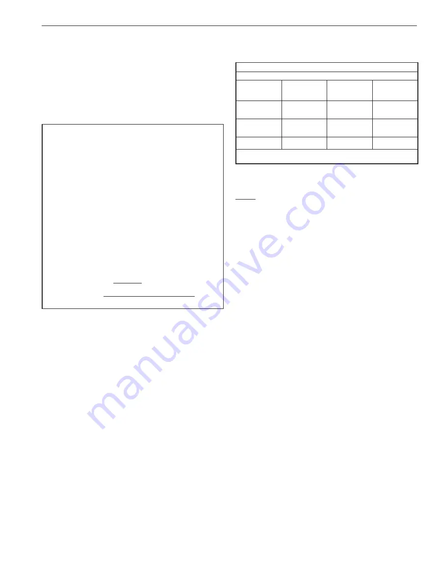
TABLE 1
REPAIR KITS
VALVE
SIZE
6” 6300
8” 530S
8” 5300
8” 6300
10” 530S
10” 5300
10” 6300
12” 530S
12” 5300
FILLED
TFE
SEATS
RKY34QA
RKY35QA
RKY36QA
VALVE
SIZE
6” 6300B
8” 530SB
8” 5300B
8” 6300B
10” 530SB
10” 5300B
10” 6300B
12” 530SB
12” 5300B
3I6SS/FILLED
TFE SEATS
RKN67WN*
RKN69WN*
RKN72WN*
* These kits contain two types of bearing spacers (28).
See Figure 5 for the proper bearing spacer to be used.
3.2
Disassembly
NOTE: If complete disassembly becomes necessary,
replacement of all seats and seals is recommended. Refer to
the Repair Kit chart on page one.
1. Follow the steps in the WARNING section before
performing any work on the valve.
2. Open and close the valve and leave in the closed position.
3. Place the valve in a vertical position with the body
cap (2) facing upward and the ball closed. (parts are
numbered per Figure 5.)
4. Remove the stem nut (15) stem nut lock (9) (if fitted),
compression ring (21) and four hex head cap screws (29).
5. Remove the stem (4) and stem retainer (30) as a
subassembly. It may be necessary to loosen with a
block of wood and hammer.
6. Press down on top of the stem (4) to remove it from the
stem retainer (30).
7. Remove the secondary stem seal (7) and the stem
bearing (8) from the stem. Pry out and discard the upper
stem seal set (32) from the stem retainer (30), BEING
CAREFUL NOT TO SCRATCH ANY SEALING SURFACES.
8. Remove and discard the stem retainer seal (25) from
the body.
9. Remove the body fasteners (11) for 6300 and 5300
valves, or (34) for 530S valves.
10. Lift the body cap (2) off of the body (1), BEING
CAREFUL NOT TO NICK OR SCRATCH THE BALL.
11. Remove the ball (3) and trunnion plates (26) as a
subassembly. (The subassembly consists of the
ball with, a trunnion plate on both ends with their
appropriate bearings and spacers.)
12. Pull each trunnion plate away from the ball and remove
the bearing spacer (28) and trunnion bearing (27).
IMO 11/17
IMO-302 EN
3
Содержание 5300
Страница 11: ...IMO 11 17 IMO 302 EN 11 ...