


7 AMI 70 en
7
Type AMI93, 94
To test sensors, use a 9-32 V DC power supply. No
series load resistor is required. Operate actuator to the
closed position. Apply power across the “FB+” and
“FB-” terminal points. Press and hold “Closed Set” but-
ton until “Closed LED is lit (2 seconds). Release button.
Operate actuator to the open position. Press and hold
“Open Set” button until “Open LED is lit (2 seconds).
Release button. Set points are retained even after
power is removed. A functioning Foundation Fieldbus
network is required to test communications.
WARNING:
Do not apply external power to the output
terminals. this will cause permanent damage to the
unit.
3.2
Fault alerts for AMI96_D
1. The OPEN green LED is lit steady when the valve is
in the open position and the open position sensor is
ON. Input Bit 3 (DI2) will be set to “1”. If the valve is
open and the LED is not lit, perform the sensor set-
ting according to instructions located in Section 3.
2. The CLOSED red LED is lit steady when the valve is
in the closed position and the closed position sensor
is ON. Input Bit 4 (DI3) will be set to “1”. If the valve is
closed and the LED is not lit, perform the sensor set-
ting according to instructions located in Section 3.
3. The SOLENOID POWER yellow LED is lit steady
when Output Bit 3 (DO2) is set to “1” to energize the
solenoid.
4. The BAD SOLENOID COIL red LED will flash at a
2Hz rate if the solenoid pilot valve coil windings are
either open or shorted. The Peripheral Fault Bit will
be set to “1”. Fault indication will clear when solenoid
pilot valve is replaced.
5. The LOW AIR SUPPLY PRESSURE red LED will flash
at a 2Hz rate if the supply pressure drops below 40
psi. Input Bit 1 (DI 0) will be set to “1”. Fault indica-
tion will clear when supply pressure goes back
above 2.8 bar.
6. The STUCK SPOOL/PILOT red LED will flash at a 2Hz
rate if after 5 seconds** of power being applied to
the coil, the internal porting pressure does not rise
above 0.7 bar. Conversely, if after 5 seconds** of
power being removed from the coil and the internal
porting pressure does not drop below 2.1 bar, a
STUCK SPOOL/PILOT fault will be indicated. For
either condition, the Peripheral Fault Bit will be set to
“1”. Fault indication will remain active until internal
porting pressure requirements are met.
7. The STUCK PROCESS VALVE/ACTUATOR red LED
will flash at a 2Hz rate if after 5 seconds** of power
being applied to or removed from the coil, the valve/
actuator does not move by a minimum of 10% of
stroke, provided there is not a STUCK SPOOL/PILOT
or LOW AIR SUPPLY PRESSURE fault already indi-
cated. Input Bit 2 (DI 1) will be set to “1”. A STUCK
PROCESS VALVE/ACTUATOR fault will also be indi-
cated if the valve/actuator doe not reach the com-
manded position within 20 seconds** (Valve open
position when solenoid coil is energized or valve
closed position when solenoid coil is de-energized).
This is also referred to as a “Stroke Time Alarm”.
Input Bit 2 (DI 1) will be set to “1”.
**NOTE:
The Factory default time settings of the Stroke
Time Alarm circuit is 20 seconds for valve Full Stroke
Time and 5 seconds for the STUCK SPOOL/PILOT and
the STUCK PROCESS VALVE/ACTUATOR diagnostic
functions.
The Stroke Time Alarm circuit timing is manually adjust-
able from 1 to 60 seconds.
When manually setting the Full Stroke Time, the sec-
ondary timing used in the STUCK SPOOL/PILOT and
the STUCK PROCESS VALVE/ACTUATOR diagnostic
functions is fixed to one half the time period of the Full
Stroke Time.
(For example: if Full Stroke Time is set to 30 seconds,
the time out for the STUCK SPOOL/PILOT and the
STUCK PROCESS VALVE/ACTUATOR diagnostic func-
tions will be 15 seconds).
See Section 3.3 for Stroke Time Alarm adjustment pro-
cedureure.
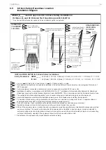
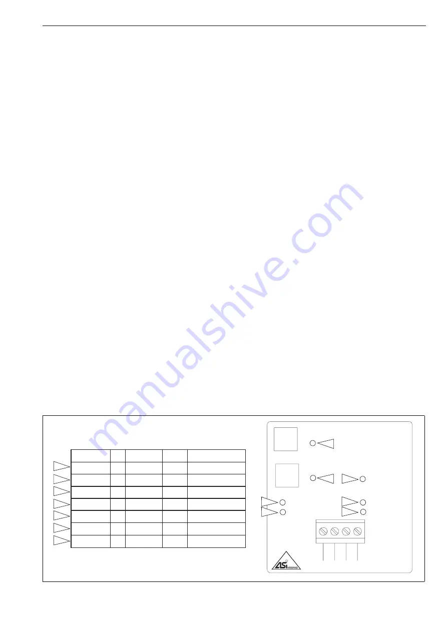
Fig. 5
Diagnostic LED Indications
ASI + (4)
ASI - (3)
SOL OUT+ (2)
SOL OUT- (1)
SET
OPEN
SET
CLOSED
OPEN
CLOSED
SOLENOID POWER
BAD SOLENOID COIL
STUCK SPOOL/PILOT
STUCK PROCESS
VALVE/ACTUATOR
LOW AIR SUPPLY
PRESSURE
Diagnostics: Blinking LED indicates problem
Setup Instructions:
Operate Actuator to Closed
Position and Push SET
CLOSED for 2 seconds.
Operate Actuator to Open
Position and Push SET
OPEN for 2 seconds
3
4
2
1
5
6
7
3
4
5
6
7
1
2
LED
LED
Color
Function
Description
Operational
State
Description
OPEN
Green
Process valve
is open
Normal
Operation
LED will be continuously lit
when process valve is open
CLOSED
Red
Process valve
is closed
Normal
Operation
LED will be continuously lit
when process valve is closed
SOLENOID
POWER
Yellow
Solenoid valve is
energized
Normal
Operation
LED will be continuously lit
when solenoid is energized
BAD SOLENOID
COIL
Red
Solenoid coil is
open or shorted
Fault State LED will flash at a 2Hz rate if
solenoid coil is open or shorted
LOW AIR SUPPLY
PRESSURE
Red
Supply air pressure
is low
Fault State LED will flash at a 2Hz rate if
supply air pressure is <40psi
STUCK SPOOL/
PILOT
Red
Solenoid valve
will not shift
Fault State LED will flash at a 2Hz rate if
solenoid valve does not shift
STUCK PROCESS
VALVE/ACTUATOR
Red
Valve/Actuator
will not turn
Fault State LED will flash at a 2Hz rate if
valve/actuator does not turn
Содержание Neles Axiom
Страница 10: ...10 7 AMI 70 en 5 DIMENSIONS E3 S1 E2 ...