


14
7 AMI 70 en
6.8
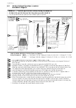
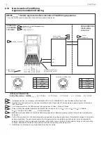
Installation Diagram for Explosive
Atmospheres for Europe
INSTALLATION NOTES for Intrinsic Safety Installations: (Ex ia IIC T5)
Entity Parameters: AMI44_____:
Ui = 16 Vdc; Ii = 25 mA ; Ci = 4.4 nF; Li = 0.0 mH; Pi = 1.0 W
IS Coil :
Ui = 28 Vdc; Ii = 120 mA ; Ci = 00 nF; Li = 0.0 mH; Pi = 1.0 W
1. Voc or Vt < Ui, Isc or It < Ii, Ca > Ci + Ccable, La > Li + Lcable.
2. Dust-tight conduit seal must be used when installed in Zone 20, Zone 21, and Zone 22 environments or where Ingress
Protection of IP67 is required.
3. Control equipment connected to barrier must not use or generate more than 250 Vrms or Vdc.
4. Installation should be in accordance with appropriate local code or practice.
5. The configuration of associated apparatus for each sensor wiring pair or solenoid wiring pair must be approved.
6. Associated apparatus manufacturer's installation drawing must be followed when installing this equipment.
7. To maintain intrinsic safety, wiring associated with each sensor or solenoid coil wiring must be run in separate cables or
separate shields connected to intrinsically safe (associated apparatus) ground.
8. Conduit Grounding - Upon installation verify electrical continuity between conduit and ground terminal.
9. Resistance between Intrinsic Safe Ground and earth ground must be less than one ohm.
10. Parts of the enclosure are non-conducting and may generate an ignition-capable level of electrostatic charge under certain
extreme conditions. The user should ensure that the equipment is not installed in location where it may be subjected to
external conditions (such as high-pressure steam) which might cause a build-up of electrostatic charge on non-conducting
surfaces. Additionally, cleaning of the equipment should only be done with a damp cloth.
11. Substitution of components may impair hazardous location safety.
Specific Conditions of Use:
1. When used within a Zone 0 location, the aluminum enclosure shall be installed in such manner as to prevent the possibility
of sparks resulting from friction or impact.
2. To prevent the risk of electrostatic sparking, the equipment enclosure shall be cleaned only with a damp cloth.
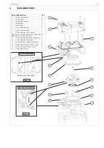
3
4
2
1
5
6
7
8
9
10
AMI44_E___* models approved for Intrinsic Safety Installations: (Ex ia IIC T5)
* Any Conduit Entry/Connector option and Visual Indicator option is approved.
HAZARDOUS
(CLASSIFIED)
LOCATION
NON-HAZARDOUS
(SAFE AREA)
LOCATION
2
4
Ex ia IIC T5
1
5
6
Intrinsic Safety Barriers
(Associated Apparatus)
3
Control
Equipment
Intrinsically Safe
Ground
9
StoneL Enclosure
10
7
Individual Sensor and solenoid coil
wiring to StoneL Axiom Models
AMI44____
8
Shields
(3) Sol2 Pwr +
(1) Sol1 Pwr +
(2) Sol1 Pwr -
(4) Sol2 Pwr -
(7)
(5) Open +
(6) Open -
(8) Closed -
Bottom Sensor
Namur Barrier
Top Sensor
Namur Barrier
Solenoid Coil
Barrier
Solenoid Coil
Barrier
AMI44 Terminal
Identifiers
(If using quick
connectors, see
Pg 3 for pin-out)
Содержание Neles Axiom
Страница 10: ...10 7 AMI 70 en 5 DIMENSIONS E3 S1 E2 ...