


6
7 AMI 70 en
3
SENSING AND COMMUNICATIONS
MODULE SENSOR SETTING
Type AMI 33, 96, 97, 93, 94
1. With the Sensor & Communication Module (CCM)
wired to the control system and power applied,
(Refer Wiring Diagram located in Section 6), operate
actuator to the closed position.
2. Press and hold “Closed Set” button until “Closed
LED is lit (2 seconds). Release button.
3. Operate actuator to the open position.
4. Press and hold “Open Set” button until “Open LED is
lit (2 seconds). Release button.
5. Set points are retained even after power is removed.
6. Sensor & Communication Modules on Axiom units
with a single solenoid have a “Solenoid Power” LED
indicating when solenoid power is applied.
Type AMI 44
1. With the Sensor & Communication Module (CCM)
wired to the control system and power applied,
(Refer Wiring Diagram located in Section 6), operate
actuator to the closed position.
2. Press and hold “Closed Set” button until “Open LED”
goes out (2 seconds). Release button.
3. Operate actuator to the open position.
4. Press and hold “Open Set” button until “Closed LED”
goes out (2 seconds). Release button.
5. Both “Open” and “Closed” LEDs will be lit during
mid-travel. Set points are retained even after power
is removed.
6. Sensor & Communication Modules on Axiom units
with a single solenoid have a “Solenoid Power” LED
indicating when solenoid power is applied.
3.1
Bench testing
Type AMI33
Power must be applied to both sensors to ensure
proper circuit operation. Use a 24 V DC power supply
with series load resistor, (2 k
Ω
- 6 k
Ω
), connected to the
24 V DC +. Operate actuator to the closed position.
Connect 24 V DC + to the “Closed C” (common) and
“Open C” (common) terminals. Connect 24 V DC - to
the “Closed NO” and “Open NO” terminals. Press and
hold “Closed Set” button until “Closed LED is lit (2 sec-
onds). Release button. Operate actuator to the open
position. Press and hold “Open Set” button until “Open
LED is lit (2 seconds). Release button. Set points are
retained even after power is removed.
To test solenoid, apply power to the “Sol Pwr IN” termi-
nals only. See warning below.
NOTE:
If using only one of the sensors for valve posi-
tion feedback, the open sensor (green) must be used.
Type AMI44
Power must be applied to both sensors to ensure
proper circuit operation. Use a 24 V DC power supply.
A series load resistor is not required when bench test-
ing. Operate actuator to the closed position. Connect
24 V DC + to the “” and “Open +” terminals.
Connect 24 V DC - to the “Closed -” and “Open -” ter-
minals. Press and hold “Closed Set” button until “Open
LED” goes out (2 seconds). Release button. Operate
actuator to the open position. Press and hold “Open
Set” button until “Closed LED” goes out (2 seconds).
Release button. Both “Open” and “Closed” LEDs will be
lit during mid-travel. Set points are retained even after
power is removed.
NOTE:
If using only one of the sensors for valve posi-
tion feedback, the open sensor (green) must be used.
Type AMI96, 97
To test sensors, use a 24 V DC power supply. No series
load resistor is required. Operate actuator to the closed
position. Apply power across the “ASI+” and “ASI-” ter-
minal points. Press and hold “Closed Set” button until
“Closed LED is lit (2 seconds). Release button. Operate
actuator to the open position. Press and hold “Open
Set” button until “Open LED is lit (2 seconds). Release
button. Set points are retained even after power is
removed. A functioning AS-Interface network is
required to test communications.
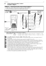
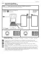
Fig. 4
Sensor and communication module (CCM)
SET
OPEN
SET
CLOSED
OPEN
CLOSED
SOLENOID
POWER
Setup Instructions:
Operate Actuator to Closed
Position and Push SET
CLOSED for 2 seconds.
Operate Actuator to Open
Position and Push SET OPEN
for 2 seconds
WARNING:
Do not apply external power to the “Sol Out” termi-
nals. This will cause permanent damage to the
unit.
CAUTION:
A series load resistor must be used when bench
testing in order to ensure proper module opera-
tion.
WARNING:
Do not apply external power to the output termi-
nals. this will cause permanent damage to the unit.
Содержание Neles Axiom
Страница 10: ...10 7 AMI 70 en 5 DIMENSIONS E3 S1 E2 ...