IC equipment
Dialysis 6.5330.100 | Dialysis Low Volume 6.5330.200
Manual
8.110.8028EN / 2018-09-07
Страница 1: ...IC equipment Dialysis 6 5330 100 Dialysis Low Volume 6 5330 200 Manual 8 110 8028EN 2018 09 07 ...
Страница 2: ......
Страница 3: ...m AG CH 9100 Herisau Switzerland Phone 41 71 353 85 85 Fax 41 71 353 89 01 info metrohm com www metrohm com IC equipment Dialysis 6 5330 100 Dialysis Low Volume 6 5330 200 Manual 8 110 8028EN 2018 09 07 ksah ...
Страница 4: ...techcom metrohm com This documentation is protected by copyright All rights reserved This documentation has been prepared with great care However errors can never be entirely ruled out Please send comments regarding possible errors to the address above ...
Страница 5: ...l connectors 6 2 4 Mode of operation for dialysis 7 3 Installation 8 3 1 Preparing the dialysis cell 8 3 2 Connecting the dialysis cell 12 3 3 Inserting the dialysis cell 16 3 4 Conditioning the dialysis system 18 4 Operation and maintenance 19 4 1 Operation 19 4 1 1 Optimizing the dialysis 19 4 1 2 Recommended procedure for the dialysis 21 4 2 Maintenance 23 5 Technical specifications 25 5 1 Dial...
Страница 6: ...Dialysis 6 5330 100 Table of figures Figure 1 IC equipment Dialysis Dialysis Low Volume Parts 4 Figure 2 Dialysis cell Parts 5 Figure 3 Dialysis cell Connectors 6 Figure 4 Stopped flow dialysis 7 Figure 5 Area transfer time diagram 20 ...
Страница 7: ...ere they are preconcentrated The ion preconcentrated acceptor solution is then subsequently injected directly into the IC system To operate the dialysis cell you need an IC system with a peristaltic pump and a cell holder as well as a Sample Processor with a peristaltic pump 1 2 Product versions The IC equipment Dialysis Dialysis Low Volume is available in the follow ing versions Table 1 Product v...
Страница 8: ...tion carefully before putting the IC equipment Dialysis Dialysis Low Volume into operation The documen tation contains information and warnings which the user must follow in order to ensure safe operation of the IC equipment Dialysis Dialysis Low Volume 1 4 Symbols and conventions The following symbols and formatting may appear in this documentation Cross reference to figure legend The first numbe...
Страница 9: ...ention to a possible hazard due to heat or hot instrument parts WARNING This symbol draws attention to a possible biological hazard CAUTION This symbol draws attention to possible damage to instruments or instrument parts NOTE This symbol highlights additional information and tips ...
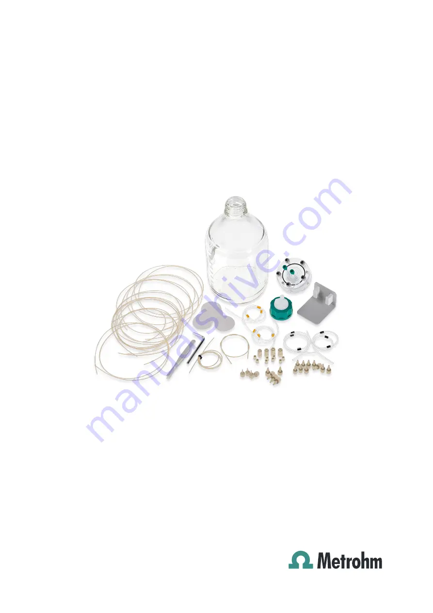
Страница 10: ...s Low Volume 4 IC equipment Dialysis 6 5330 100 2 Overview 2 1 Parts of the IC equipment Dialysis Dialysis Low Volume Figure 1 IC equipment Dialysis Dialysis Low Volume Parts Parts of IC equipment Dialysis Parts of IC equipment Dialysis Low Volume ...
Страница 11: ...equipment Dialysis 6 5330 100 5 2 2 Parts of the dialysis cell Figure 2 Dialysis cell Parts 1 Stopper 2 Donor chamber 3 Sealing ring 4 Acceptor chamber 5 Washers 6 Screws For joining the acceptor and the donor chamber ...
Страница 12: ... 3 Dialysis cell connectors Figure 3 Dialysis cell Connectors 1 Donor chamber 2 Acceptor chamber 3 Outlet Sample 4 Inlet Sample 5 Inlet Acceptor solution 6 Outlet Acceptor solution NOTICE The product number 6 2729 200 is only engraved in the Low Volume dialysis cell ...
Страница 13: ...ng phase the acceptor flow is stopped Because of the con centration gradient the ions pass through the membrane The acceptor flow remains stationary until a concentration equilibrium is achieved between the two cell halves The concentration in the acceptor solution thus matches the concentration of the original sample Afterwards the acceptor solution is injected directly into the ion chromatograph...
Страница 14: ...ristaltic pump and a cell holder then place the dialysis cell in the cell holder If you are working with an ion chromatograph that has a peristaltic pump but no cell holder then place the dialysis cell holder 6 2057 130 in the detector chamber of your ion chromatograph 3 1 Preparing the dialysis cell Required tools Dialysis cell Dialysis cell 6 2729 100 Low Volume dialysis cell 6 2729 200 Dialysis...
Страница 15: ...ysis cell Remove the sealing ring 4 Cleaning the dialysis cell CAUTION Damage to the dialysis cell Organic solvents e g acetone corrode and damage the dialysis cell material PMMA Use only ultrapure water or a water ethanol mixture 70 30 for cleaning the dialysis cell For samples that contain organic components e g solvents use the PEEK dialysis cell 6 2729 120 This cell has an excellent chemical r...
Страница 16: ...tecting the filtration membranes Do not place it in the dialysis cell The thin light blue sheets are separation sheets placed between two filtration membranes Do not place them in the dialysis cell The thin white sheets are the dialysis membranes Use only these for dialysis Using the tweezers take a new dialysis membrane out of the package Place the dialysis membrane in a petri dish filled with ul...
Страница 17: ...sealing ring onto the cell 7 Assembling the dialysis cell Place the upper part of the dialysis cell on the lower part in such a way that the two guide bolts fit exactly into the two bore holes 8 Screwing the dialysis cell together Screw the five screws with the washers in the dialysis cell by hand first Then firmly tighten them with the hex key in crosswise sequence ...
Страница 18: ...eristaltic pump in the manual for the Sample Processor or the ion chromatograph for this information Parts of IC equipment Dialysis Parts of IC equipment Dialysis Low Volume Connections for acceptor solution Required accessories Dialysis cell Dialysis cell 6 2729 100 Low Volume dialysis cell 6 2729 200 PTFE capillary 0 5 mm ID 1 m 6 1803 040 Pump tubing LFL orange yellow 3 stoppers 6 1826 320 Pump...
Страница 19: ...or the sample Use the two pump tubings with black stoppers 6 1826 340 for con veying the sample Proceed as follows for each tubing Attach the coupling olive UNF 10 32 6 2744 034 to the inlet Attach the pump tubing connection with locking nut 6 2744 160 to the outlet see chapter Installing the peristaltic pump in the manual for the ion chromatograph or in the man ual for the Sample Processor 2 Prep...
Страница 20: ...n a PTFE capillary 0 5 mm ID 1 m 6 1803 040 to the outlet of the pump tubing with black stoppers 6 1826 340 using a pressure screw 6 2744 070 Tighten the other end of the PTFE capillary to the sample inlet of the dialysis cell 3 4 using a pressure screw 6 2744 000 4 Connecting the sample outlet Tighten a PTFE capillary 0 5 mm ID 1 m 6 1803 040 to the sample outlet of the dialysis cell 3 3 using a ...
Страница 21: ...let of the pump tubing with orange yellow stoppers 6 1826 320 using a pressure screw 6 2744 070 Immerse the other end of the PTFE capillary in the vessel contain ing the acceptor solution 6 1808 070 with 6 1602 150 and fas ten with a PVDF pressure screw 6 2744 000 Tighten another PTFE capillary 6 1803 040 to the outlet of the pump tubing with orange yellow stoppers using a pressure screw 6 2744 07...
Страница 22: ...a pressure screw 6 2744 010 Tighten a PTFE capillary 0 5 mm ID 1 m 6 1803 040 to the sample outlet of the injection valve Port 2 using a pressure screw 6 2744 010 Tighten the other end of the PTFE capillary to the inlet of the sec ond pump tubing with orange yellow stoppers 6 1826 320 using a pressure screw 6 2744 070 Tighten another PTFE capillary 0 5 mm ID 1 mm 6 1803 040 to the outlet of the se...
Страница 23: ...l holder 6 2057 130 Insert the dialysis cell with the dialysis cell holder into the detector chamber of the ion chromatograph Inserting the dialysis cell into the cell holder horizontally If the ion chromatograph is not equipped with a cell holder then the dial ysis cell with the dialysis cell holder 6 2057 120 can be used 1 Insert the dialysis cell into the dialysis cell holder 6 2057 120 Insert ...
Страница 24: ...mps see the chapter Installing the peristaltic pump in the manual for the ion chromatograph or the Sample Processor 3 Conditioning the dialysis system Rinse the dialysis system with ultrapure water for 20 min Check whether equal amounts of solution are emerging from both feed lines to the waste container Check whether all capillary connections are tight If liquid is escaping somewhere then tighten...
Страница 25: ...er time should be determined for each analysis prob lem on the basis of measurements of the individual ion concentrations in relation to the transfer time and periodically verified 1 Initial measurement Set the following values in the software Dialysis cell 6 2729 100 Transfer time 15 s Dialysis time 10 min Low Volume dialysis cell 6 2729 200 Transfer time 10 s Dialysis time 6 min Immerse the samp...
Страница 26: ...sis time must be determined This time depends on the total ion concen tration in the sample The dialysis time is the time during which the acceptor flow is stopped and only sample is pumped This time must be chosen in such a way that 100 of the sample concentration is achieved in the acceptor solution For the dialysis cell 6 2729 100 with the dialysis membrane 6 2714 010 Cellulose acetate thicknes...
Страница 27: ...e sample aspiration capillary in the standard solution used in step 1 Start a determination in the software and wait until the chromato gram has been evaluated 3 Additional measurements Increase the dialysis time in the software by 1 minute each time and start the determination Repeat the measurements until the measured values are stable 4 Determining the optimum dialysis time The recovery rates c...
Страница 28: ...cceptor solution and the rins ing solution for approx 10 minutes and then switch off the peri staltic pumps again 5 Calibrating the IC system Immerse the sample aspiration capillary in the standard solution Start the determination in the software and wait until the stan dard chromatogram has been evaluated Repeat the two steps for all standard solutions 6 Determining the sample Immerse the sample ...
Страница 29: ...d if the signal intensity during dialysis decreases if the dialysis membrane dries out if the dialysis membrane becomes damaged as a result of depositions or bacterial growth if the sample channel is blocked i e the sample can no longer be pumped through the dialysis cell Replacing the dialysis membrane 1 Disassembling the dialysis cell Unscrew the four capillaries from the dialysis cell and remov...
Страница 30: ... to the dialysis cell inlet for the acceptor solution 3 5 using a PVDF pressure screw 6 2744 000 Tighten the acceptor outlet capillary to the dialysis cell outlet for the acceptor solution 3 6 using a PVDF pressure screw 6 2744 000 4 Conditioning the dialysis system see chapter 3 4 page 18 ...
Страница 31: ...xture 70 30 no other organic solvents 5 2 Low Volume dialysis cell 6 2729 200 Material PMMA poly methyl methacrylate Solvent compati bility Water or water ethanol mixture 70 30 no other organic solvents 5 3 Dialysis membrane 6 2714 010 Pore diameter 0 20 µm Membrane diame ter 47 mm Material Cellulose acetate 5 4 Dialysis membrane 6 2714 030 Pore diameter 0 15 µm Membrane diame ter 47 mm Material P...
Страница 32: ...r Internet browser 2 Enter the article number e g Dialysis Low Volume 6 5330 200 into the search field The search result is displayed 3 Click on the product Detailed information regarding the product is shown on various tabs 4 On the Included parts tab click on Download the PDF The PDF file with the accessories data is created NOTICE When you receive your new product we recommend downloading the a...
Страница 33: ...of operation 7 Optimize 19 Dialysis cell Connectors 6 Parts 5 Prepare 8 Dialysis system Condition 18 Connect 12 Dialysis time Determine 20 I Installation 8 M Maintenance 23 O Operation 19 Operation and maintenance 19 P Product versions 1 R Rinsing time Determine 19 T Technical specifications 25 Transfer time Determine 19 ...