


6
OPERATION
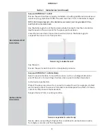
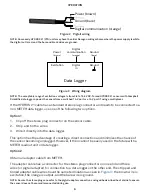
Ground (bare)
Digital communication (orange)
Power (brown)
Figure 2 Pigtail wiring
NOTE: Some early HYDROS 21 (CTD) units may have the older Decagon wiring scheme where the power supply is white,
the digital out is red, and the bare and black wires are ground.
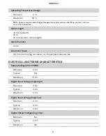
Excitation
Digital
in
Data Logger
Ground
Digital
communication
(orange)
Ground
(bare)
Power
(brown)
Figure 3 Wiring diagram
NOTE: The acceptable range of excitation voltages is from 3.6 to 15.0 VDC. To read HYDROS 21 sensors with Campbell
Scientific data loggers, power the sensor from a switched 12-V port or a 12-V port if using a multiplexer.
If the HYDROS 21 cable has a standard stereo plug connector and needs to be connected to a
non-METER data logger, use one of the following two options.
Option 1
1. Clip off the stereo plug connector on the sensor cable.
2. Strip and tin the wires.
3. Wire it directly into the data logger.
This option has the advantage of creating a direct connection and minimizes the chance of
the sensor becoming unplugged. However, it then cannot be easily used in the future with a
METER readout unit or data logger.
Option 2
Obtain an adapter cable from METER.
The adapter cable has a connector for the stereo plug connector on one end and three
wires (or pigtail adapter) for connection to a data logger on the other end. The stripped and
tinned adapter cable wires have the same termination as seen in
: the brown wire is
excitation, the orange is output, and the bare wire is ground.
NOTE: Secure the stereo plug connector to the pigtail adapter connections using adhesive-lined heat shrink to ensure
the sensor does not become disconnected during use.