background image

Theory 


TWRF1 SCR Power Controller 

18 

Ametek HDR Power Systems 

Rev 2 


4.6 

SPAN and ZERO Controls 

The  ZERO  and  SPAN  potentiometers  are  screwdriver  adjustable.    The  center  position  of  the  ZERO 
control corresponds to zero bias and zero power output.  The approximate zero setting can be found 
by rotating the control over its range, stopping near the midpoint of rotation.  The precise zero setting 
can  be  found  by  observing  the  output  level  while  rotating  the  control  near  the  midpoint  of  rotation.  
From the midpoint to extreme CCW (counterclockwise) is the zero  or negative region. Operating the 
control in  this region, one can zero the output from the TWRF1  at any output  level of a  temperature 
controller or other external control device.  From midpoint to extreme CW is the positive control region, 
whose extremes correspond to 0% and 100% power output, respectively, as manually adjusted. 


The SPAN control is used as a final adjustment to set the TWRF1 output to precisely 100%, when the 
principal control device (external controller, external “manual” control or ZERO potentiometer) is set to 
demand 100% output. 
 

4.7 

Voltage-Squared Feedback 

Voltage-squared feedback simulates power feedback.  It is used to help maintain constant power 
delivered to the load when the line voltage changes and the load resistance remains constant. 


4.8 

Shut-down 

The  shutdown  circuit  provides  a  quick  SCR  shutdown  signal.    This  is  accomplished  via  a  customer 
provided  contact  across terminal 3  and  terminal 4.    This removes the input  signal  to  the  comparator 
that tells the circuit when to gate the SCRs on.  It also instantaneously turns off the SCR gating pulses. 


Содержание TWRF1 SCR Series

Страница 1: ...tion and Maintenance Manual Number 9100051 Revision 2 530 Lakeview Plaza Blvd Ste C Worthington Ohio USA 43085 Toll Free 1 888 PWR CNTL 797 2685 Phone 614 308 5500 Fax 614 308 5506 Web www hdrpower co...

Страница 2: ...presentative nearest you please call Ametek HDR Power Systems main office at 614 308 5500 Revision 1 December 2017 Initial Release Revision 2 Aug 2022 General Revision 2022 by Ametek HDR Power Systems...

Страница 3: ...mote Manual Control with a Potentiometer 11 3 4 Process Command Input Control 12 3 5 Auto Manual Control with a Controller and Remote Potentiometer 13 3 6 On Off Control 14 3 7 Shutdown 14 3 8 Overcur...

Страница 4: ...wer Controller ii Ametek HDR Power Systems Rev 2 7 1 Warranty 24 7 2 In house Repair Services 24 7 3 Field Service Repairs 25 APPENDIX 26 Appendix A System Schematic 26 Appendix B 30 60 A Outline 27 A...

Страница 5: ...ut Connections 13 Figure 3 4 Auto Man Control with Controller and Remote Potentiometer 13 Figure 3 5 On Off Control 14 Figure 3 6 Shutdown Control 14 Figure 3 7 Current Limit Trip Board 15 Figure 4 1...

Страница 6: ...Table of Contents TWRF1 SCR Power Controller iv Ametek HDR Power Systems Rev 2...

Страница 7: ...anch circuit fused disconnect or circuit breaker with this Power Controller is required to ensure the safety of operating personnel CAUTION HAZARDOUS VOLTAGES exist at the Power Controller Load AT ALL...

Страница 8: ...Safety Instructions TWRF1 SCR Power Controller 2 Ametek HDR Power Systems Rev 2...

Страница 9: ...the SCRs is controlled by a digital firing control circuit synchronized in phase with line frequency either 50 or 60 Hz A soft start approximately a 1 cycle ramp feature is standard that allows the Po...

Страница 10: ...ch the output can increase to prevent high inrush currents with transformer coupled loads or high cold to hot resistance ratios such as tungsten heating elements The rate of increase is limited to app...

Страница 11: ...red Power output linearity versus control signals input 2 Non isolated 5 Isolated Power SCRs protection Current surge Subcycle I T semiconductor fuse OPTIONAL Transient voltage spikes dv dt Metal Oxid...

Страница 12: ...Description TWRF1 SCR Power Controller 6 Ametek HDR Power Systems Rev 2...

Страница 13: ...15 30 A and 10 AWG or larger wire for the other sizes NOTICE Use copper conductors rated 75 C minimum for all model current ratings On the internal side of the TWRF1 the wire from L2 should connect to...

Страница 14: ...nal Input HDR s TWRF Phase Fired SCR Power Controllers are configured for a potentiometer non isolated but has the capability of having either an isolated current or non isolated voltage Command Signa...

Страница 15: ...cedure as follows 1 Open the SCR power controller and locate transformer T1 The primary side of T1 transformer will contain two wires one black the other white and black Refer to figure 2 3 Figure 2 3...

Страница 16: ...Operation TWRF1 SCR Power Controller 10 Ametek HDR Power Systems Rev 2...

Страница 17: ...icator The Command Signal Indicator is a green Light Emitting Diode LED located on the front cover of the unit The brilliance of this LED will change with a current Command Signal The brilliance incre...

Страница 18: ...ge reading is at maximum h If necessary readjust ZERO with remote potentiometer fully CCW and SPAN control and remote potentiometer fully CW i Turn off the line power to the TWRF1 and disconnect the t...

Страница 19: ...eter CW until the output trips to the desired level 3 5 Auto Manual Control with a Controller and Remote Potentiometer On closed loop processes it may be desirable to be able to operate the unit manua...

Страница 20: ...enable the TWRF1 Figure 3 5 On Off Control Calibrate the system by performing the steps in 3 3 Note that zero power demand is accomplished by opening the contacts with the controller and maximum powe...

Страница 21: ...Adjust the OC CUR PWR potentiometer fully CW b With the power controller at full output adjust OC CUR PWR potentiometer CCW until the unit shuts off c Adjust the OC CUR PWR potentiometer slightly CW d...

Страница 22: ...Operation TWRF1 SCR Power Controller 16 Ametek HDR Power Systems Rev 2...

Страница 23: ...ing of the SCRs is controlled by a digital firing control circuit synchronized to the line frequency 50 or 60 Hz The firing control circuit may be manually controlled by the built in ZERO control or a...

Страница 24: ...rnal control device From midpoint to extreme CW is the positive control region whose extremes correspond to 0 and 100 power output respectively as manually adjusted The SPAN control is used as a final...

Страница 25: ...riable from zero to some intermediate value but cannot be brought to maximum The symptoms listed may be caused by one or more of the following an environmental problem faulty input power or load conne...

Страница 26: ...ns should be free of dust or dirt for proper heat transfer and free of obstructions which could prevent proper airflow Contamination The unit should be periodically cleaned of all dust and dirt Howeve...

Страница 27: ...n the Rx1 scale the resistance should be infinite in both directions If a shorted component is indicated in any of these cases replace it 2b Firing control section defective Replace the fuse and retur...

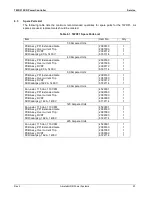
Страница 28: ...rrange for service at your site or by shipment to Ametek HDR Power System as you request We will make every possible attempt to support your emergency on site needs regardless of how contacted 6 2 Spa...

Страница 29: ...0 2087000 2099112 6791114 1 1 1 1 60 Ampere Units PCB Assy PF1 Extended Gate PCB Assy Over current Trip PCB Assy DVDT SCR dual pkg 1622 A 1400 V 2099160 2087000 2099112 6722114 1 1 1 1 90 Ampere Units...

Страница 30: ...Y OR OTHERWISE IN NO EVENT WILL AMETEK HDR BE LIABLE FOR INCIDENT OR CONSEQUENTIAL DAMAGES NOR IN ANY EVENT SHALL HDR S LIABILITY EXCEED THE UNIT PRICE OF ANY DEFECTIVE PRODUCT OR PART 7 2 In house Re...

Страница 31: ...Power Systems 25 7 3 Field Service Repairs Repairs may be performed at your location Please contact Ametek HDR Power Systems at 614 308 5500 to discuss terms and conditions to get the current service...

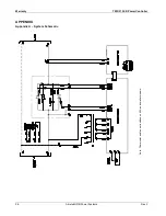
Страница 32: ...Warranty TWRF1 SCR Power Controller 26 Ametek HDR Power Systems Rev 2 APPENDIX Appendix A System Schematic Note Thermostat and fan not included on 60 A and smaller models...

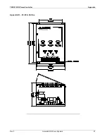
Страница 33: ...TWRF1 SCR Power Controller Appendix Rev 2 Ametek HDR Power Systems 27 Appendix B 30 60 A Outline R...

Страница 34: ...Warranty TWRF1 SCR Power Controller 28 Ametek HDR Power Systems Rev 2 Appendix C 90 225 A Outline R...

Страница 35: ...Notes...

Страница 36: ...530 Lakeview Plaza Blvd Ste C Worthington Ohio 43085 USA...

Отзывы: