55
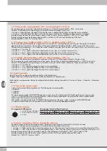
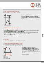
3.3.5.2 Signal Range - Signal_RangeAO_x_I5F60_Sxx
Each channel can be configured with a type of output signal.
The following types are available:
• Init value = 0 OFF
• Init value = 1 0..10 VDC
• Init value = 2 - 10/+10 VDC
• Init value = 3 0…5 VDC
• Init value = 4 -5 / +5 VDC
• Init value = 6 0…20 mA
• Init value = 7 4…20 mA
If the channel is not used, it can be disabled by selecting OFF to avoid any disturbances.
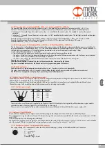
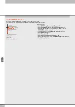
3.3.5.3 User full scale - UserFullScaleAO_x_I5F61_Sxx
These two values can be set to change the scale of numerical values sent to the control system to obtain a value of the output analogue signal.
The 15-bit signal conversion system plus the sign can be used to set values from – 32768 to +32767.
In case of need these values can be reduced.
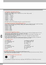
3.3.5.4 Minimum monitor - MonitorLowestValueAO_x_I5F62_Sxx
It is used to verify whether the value received by the Master is consistent with the value set under LowestValueScaleAO_x_I5F64_Sxx.
3.3.5.5 Maximum monitor - MonitorHighestValueAO_x_I5F63_Sxx
It is used to verify whether the value received by the Master is consistent with the value set under HighestValueScaleAO_x_I5F65_Sxx.
3.3.5.6 Minimum value - LowestValueScaleAO_x_I5F64_Sxx / HighestValueScaleAO_x_I5F65_Sxx
Values used for the monitor function.
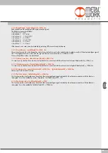
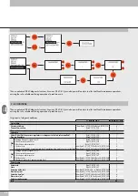
3.3.5.7 Fail Safe Output - FailSafeOutputAO_x_I5F66_Sxx
This function can be used to determine the value of the output analogue signal individually when the communication with the Master is
interrupted. It must be enabled by System Parameters – FailSafeOutput_I5F01_S01.
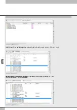
3.3.5.8 Fault mode value - FaultModeValueAO_x_I5F67
This function can be used to determine the value of the output analogue signal individually when the communication with the Master is
interrupted. It must be enabled by FailSafeOutputAO_x_I5F66_Sxx.
Содержание EB 80 ETHERNET POWERLINK
Страница 1: ...MANUALE D USO USER MANUAL ...


