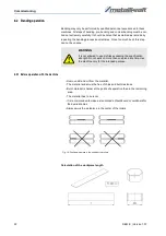
Commissioning
RBM E | Version 1.07
27
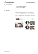
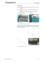
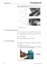
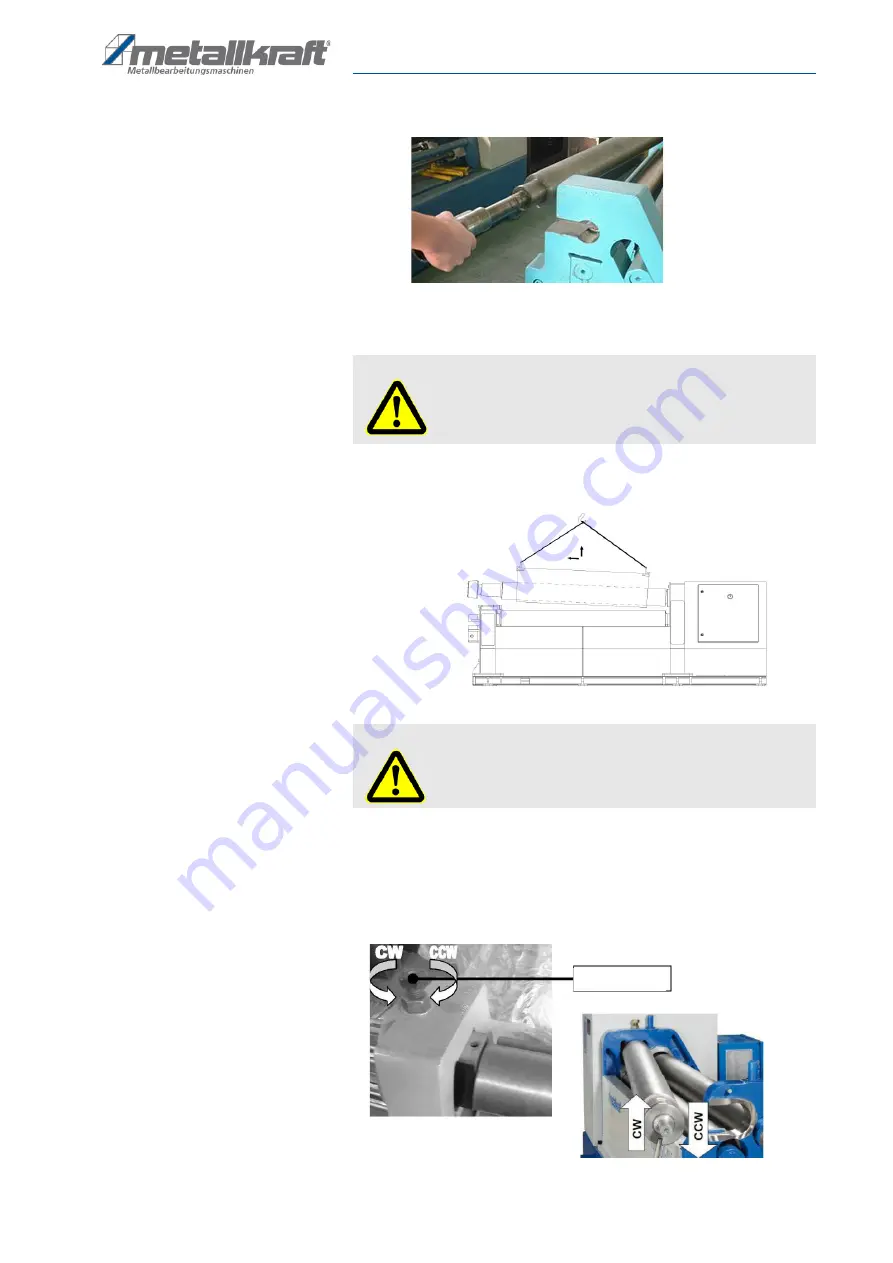
Step 4: Swing top roller (Fig. 21).
Fig. 21: Swing the top roller
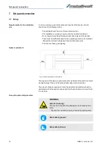
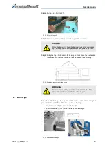
Step 5: Remove workpiece. Use a crane to support the workpiece.
Step 6: Swing the top roller back into the bearing and lock it with the mechanical
lock. Make sure that the mechanical lock has been made correctly.
Fig. 22: Workpiece removal with lifting device
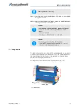
8.2.8 Counterweight
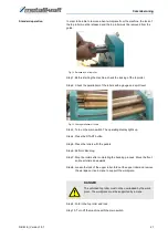
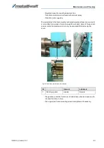
At the top of the housing of the top roller is the screw for the balance weight. It
prevents the top roller from tilting too far when extending.
- Turn clockwise (CW) for more counterweight.
- Counterclockwise (CCW) turning for less counterweight.
Fig. 23: Adjust balance weight
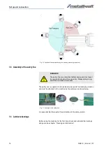
DANGER
When the top roller is tilted, the top roller must not be overloaded
by the workpiece. The workpiece must be supported by a crane.
WARNING!
Do not change safety device. Never try to activate a func
-
tion of the machine when the top roller is open.
Screw

