12
®
CAT10090V - NLFRENES - v1.0 - 15082014
EN
Save this manual
Read and understand all instructions of this manual before use. Keep the manual nearby the device for future reference.
1 Technical specifications
Height bender
965 mm
Net weight bender
26 kg
Bending capacity flat steel
8 x 30 mm - 6 x 50 mm
Bending capacity round steel
16 mm
Bending capacity square steel
16 x 16 mm
Bending capacity concrete steel
12 mm
Die sizes
1’’ - 1 1/4’’ - 1 1/2’’ - 1 3/4’’ - 2’’ - 2 1/2’’ - 3’’
2 Safety
• Keep the working space clean and clear.
• Keep children and unauthorized persons away from the working space.
•
Do no operate the tool if under the influence of alcohol, drugs or medicines, if you feel very tired of if you suffer from
a disease that reduces your concentration.
• Keep hands away from mobile parts.
•
Always wear safety goggles. Wear close-fitting clothing, gloves and safety shoes.
• Keep proper footing and balance at all times.
• Stay alert. Watch what you are doing.
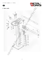
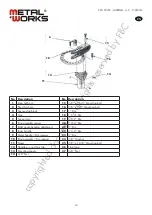
• When servicing, only use original spare parts.
• When not in use, store the device in “closed” position in a dry location to reduce rust.
• Make sure the device is securely mounted to a stable surface.
• Do not exceed the capacity of the bender. Do not use an extension bar and do not modify the bender.
•
Before use, make sure that all pins are firmly inserted.
•
Make sure the stock is of sufficient length. Stock must extend far enough between the stop block and the forming die
so as not to slip and cause injury.
3 Assembly
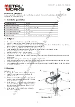
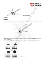
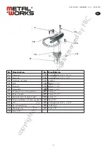
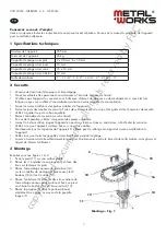
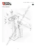
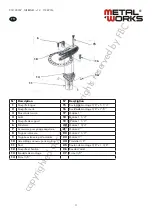
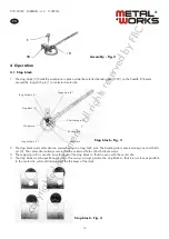
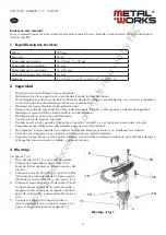
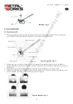
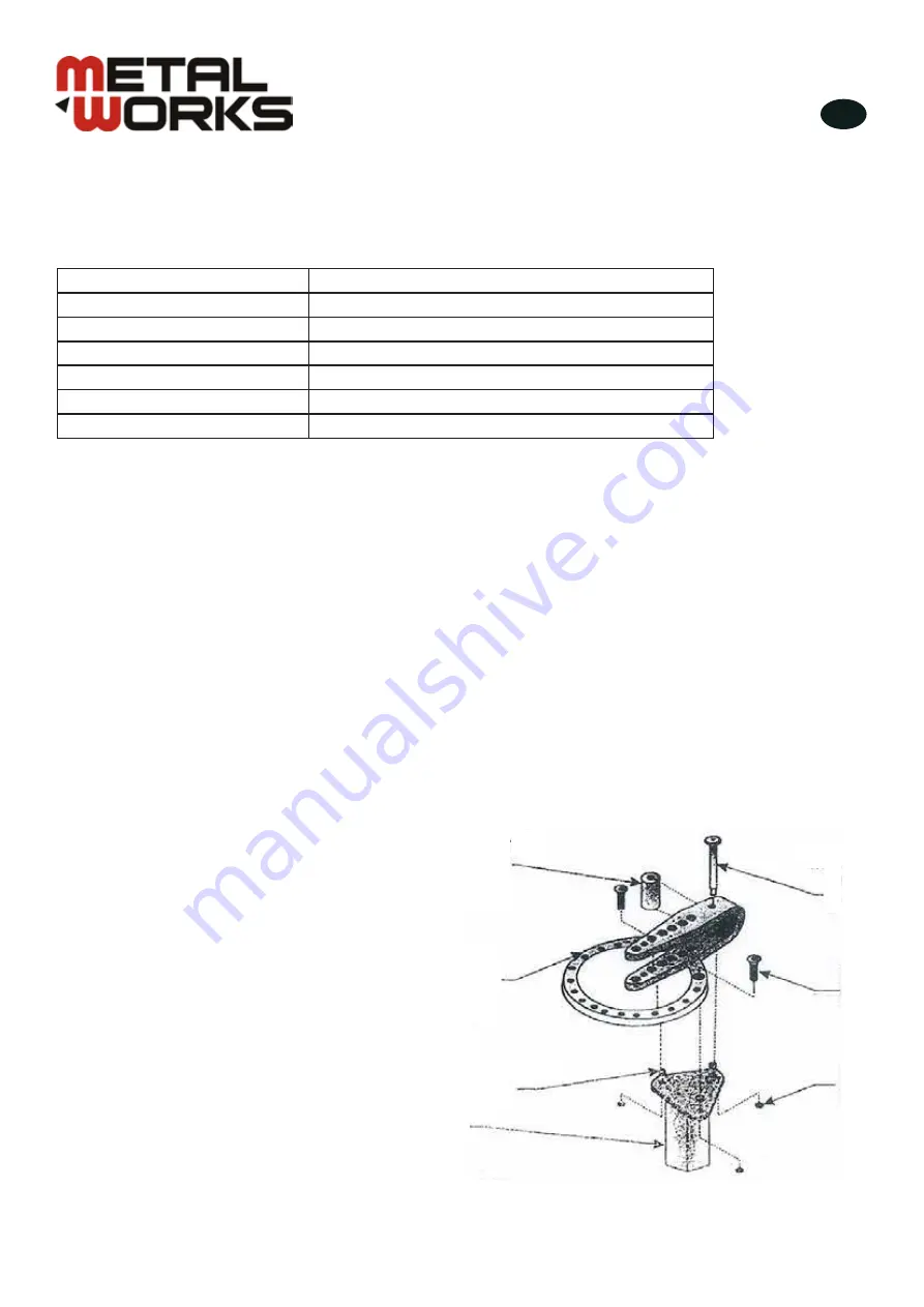
See figures 1 and 2.
1. Bolt the stand (11) to a stable surface.
2. Place three mounting spacers (13) over the three
holes on the top of the stand.
3. Place the ring assembly/die receiver (10) over the
three mounting spacers and secure using the two
bolts (16) and two nuts (14).
4. Place the ring assembly spacer (6) between the
back two holes of the ring assembly and secure the
entire assembly to the stand using the mounting bolt
(15) and remaining nut (14).
5. Place the handle die receiver (9) between the
assembly spacer die receiver and secure in place
using the long hitch pin (1).
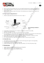
Assembly - Fig. 1
10
16
11
14
15
13
6
copyrighted
document
- all
rights
reserved
by
FBC


