
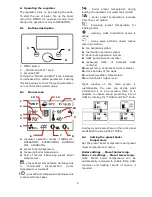


22
In case of using the version with STB
device before making the montage
and
wiring
it
is
strongly
recommended to take out the STB
capillary from inside the clamp box
using cable opening as described on
the picture below.
Attention! This capillary cannot
be smashed or bend with acute
angle.
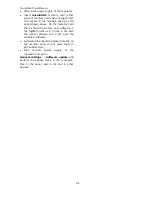
1- Cable opening 2 – The STB capillary cable,
which was being correctly taken out from the clamp
box.
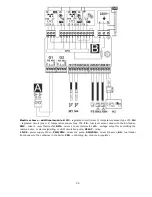
12.4
IP protection rate
The regulator casing provides the IP20
protection rating. The casing on the
connectors cover side provides IP00 rating,
and because of that connectors must be
unconditionally covered with the cover.
If there is a need to gain an access to the
terminals side, it is a must to disconnect the
mains voltage and make sure there is no
dangerous voltage on regulator terminals.
12.5
Electric connection
The regulator is designed to be fed with
230V~, 50Hz voltage. The electrical system
should be:
three core (with protective wire PE),
in accordance with applicable regulations.
Caution: After the regulator is
turned off using the keyboard,
dangerous voltage can occur on the
terminals. Before starting any
assembly
works,
you
must
disconnect the mains supply and
make sure that there is no
dangerous voltage on the terminals
and the leads.
Connection cables should not have contact
with surfaces which temperature exceeds
cables nominal operating temperature.
Terminals 1-22 are designed to connect
devices supplied by the mains 230V~ voltage.
Terminals 25–48 are designed to work with
low-voltage devices (<12V).
Connection of the 230V~ mains
voltage to terminals 25-48 or to
transmission terminals G2, G3, B
and USB results in the regulator
damage and poses a threat of
electrocution.
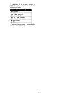
Tips of connection cables, especially mains
voltage cables should be secured from
splitting by e. g. insulated clamp sleeves in
accordance with the picture below: a –
properly secured, b – improperly secured.
Unconditionally check if any lead of
the insulated cable, or the cable
itself DO NOT have electrical
connection
with
the
metal
grounding strip (which is placed
near to high voltage terminals of the
regulator).
The feeder cable should be connected to the
terminals marked with an arrow.
All peripherals (such like: pumps,
RE-marked relays and connected
recipients) may be connected only
by qualified person in accordance
with applicable regulations. Safety
precautions to prevent electrocution
shall be observed.
Regulator shall be equipped with a
set of pins connected to 230V AC
mains.
Protection lead of the power supply cable and
protection leads of connected devices should
be connected to the grounding strip placed
Insulated clamp sleeve, 6mm lenght.
Содержание ecoMAX 860P
Страница 6: ......
Страница 7: ...INSTRUCTION MANUAL ecoMAX 860P...
Страница 16: ...16...
Страница 17: ...17 INSTALLATION AND SERVICE SETTINGS ecoMAX 860P...
Страница 44: ...44...
Страница 45: ......
Страница 46: ......
Страница 47: ......
Страница 48: ...Jacek Kucharewicz ul Sikorskiego 66 16 100 Sok ka Poland tel 48 85 711 94 54 www metalfachtg com pl...


